Like it or not, Hackers gonna hack. And when your hackerspace has someone who looks like Doc Brown from Back to the Future, the builds can get a bit weird, like this Hack42 FestivalCharger.
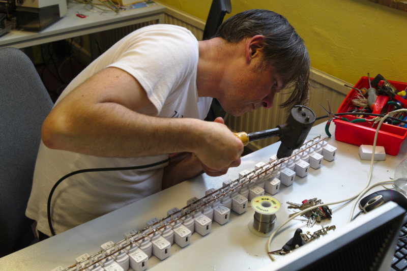
The Hack42 hackerspace in Arnhem, The Netherlands had collected a large number of TP-Link 5V USB chargers – but all of them had the North American NEMA plug (flat, 2 pin) which wouldn’t fit the Schuko sockets prevalent in The Netherlands. [Simon “MacSimski” Claessen] decided to whip out his giant soldering iron and use it to solder two long pieces of welding filler metal rods to 33 of the chargers, effectively wiring them up in parallel. He did apply his obvious skill and experience to good use. For one, the diameter of the filler metal rods he used were just about the right size to fit in the Shucko Schuko socket. And the gap between the two turned out to be the right distance too, thus creating a sort of Schucko Schuko plug. All that was needed to power up all the chargers was to connect a socket extension to the FestivalCharger. The unit was built to allow crowds of festival-goers to charge their phones and battery-powered gadgets simultaneously. To make sure the visitors didn’t get electrocuted, he used a piece of PVC pipe to cover up the exposed pins and keep it all safe.
Thanks to Hack42 member [Dennis van Zuijlekom] for sending in this tip.


At first I thought this was going to use a scary amount of power.
33 chargers, 5V @ 1A = 165 watts max. Assuming 85% efficiency on these (IRL its probably higher), that is just under 200 watts total. Not bad at all.
Apparently the average efficiency of these chargers would be closer to 66%
http://www.righto.com/2012/10/a-dozen-usb-chargers-in-lab-apple-is.html
Great article, thanks!
Schuko is an abbreviation for the German word Schutzkontakt (protective earthing) and only applies to the round plugs that actually have the third protective earthing contact.
https://en.wikipedia.org/wiki/Schuko
The “typically” European plugs with only two contacts (liki those used for USB chargers) are called Europlug (or Eurostecker in German).
https://en.wikipedia.org/wiki/Europlug
Schuko outlets do accept Europlugs.
You really have 3 different spellings for Schuko in your post and Schuko is not even the right name for the plug you mean.
Thanks – you spared me the hassle of typing in the same meaning with different words. Sigh. Back to bed :-)
Every normal connector ever :)
https://en.wikipedia.org/wiki/IEC_60320
Cool project!
Now lets see some data line hook ups and a rubberducky (or similar MCU) capable of pwning any phone or tablet connected! Mwuahaha
USB data line*
I’m sure it would have been cheaper and more efficient to just wire up a bunch of usb fs with a few resistors and a power supply
It would have been.
Not if you’ve already got the USB chargers.
Who just has 33 wall charges that can charge modern phones?
The Hack42 Hackerspace. Well…they used to. Now they have a 33 port FestivalCharger.
We still have 33 USB power supplies as well as the Festivalcharger. And another 33 power supplies. And yet 33 more power supplies. Then when I say we would have another 33 power supplies you’d think that may be the end of it but you’d be wrong.
– I don’t even want to think about the inrush current simultaneously charging the input bulk capacitors (rectified AC voltage is around 170V DC) for all 33 wall warts.
– Non Earth grounded AC wallwart are know to have some amount of leakage current. The wallwarts on the opposite side have reverse Neutral/Live connection. What happens if someone touches the case or the USB cable shields of two devices – connected to each of the two side?
– Is there a fuse at the end of this bussed connection or does it relies on the upstream fuse of the AC outlet it plugged into?
tekkieneet, exactly what I was thinking!
I was more worried about keeping that long power bus with 230VAC insulated from the casual plugger/unplugger but it looks like they just filled the whole thing up with hot glue to fix that.
The inrush current probably lasts so short that it’s not going to heat up anything enough to cause damage, especially when nothing is plugged into the chargers when they turn it on.
I’m not an electrician but I would think on a double insulated device (any legal device without a ground connection), leakage current from the primary circuit to the secondary circuit should be so little that it’s not going to hurt if you would touch the ground outputs of any two wall-warts that are plugged in in opposite phase. If it does turn out to be a concern, they could always go in and connect all the output grounds together. Judging from the pictures, the adapters they used aren’t polarized anyway so plugging in two adapters in opposite direction could happen in normal non-hackerspace environments too (European plugs are never polarized, by the way, and I understand that the polarized NEMA plug is a relatively recent development too so I wonder how much anyone should worry about that sort of thing anyway).
From the pictures, I can see that the adapters have a 0.3A max rating for the primary circuit, so the theoretical maximum current through the entire circuit is 10A. I have a funny feeling that that’s why they decided on the number of 33 adapters on one circuit (that master switch that they used is probably rated for 10A). But that max primary current rating is based on the lowest possible input voltage of 100V and they’re running it at 230V so it probably never draws more than 5A. Building circuit fuses are usually 16A in the Netherlands and it takes a LOT to blow one. Like spinning up two 56kg/120lbs mainframe hard disks at the same time, for example (don’t ask me how I know ;-)
polarized NEMA plugs have been around for at least 25 years, I have a TV dated that and has polarized plug to reduce risk of accident when the TV is being serviced. It’s rare to find non-polarized plug in USA these day, even cheap Christmas light are usually polarized.
They can do what they want in the US (unfortunately enough..) but in western europe only the brits do polarized plugs AFAIK.
Although the mains wiring does often follow a standard I think, but you could not tell as end-user.
As well as the UK, Switzerland, France and Denmark have sockets with asymmetric ground contacts, so they can be polarised (don’t know off the top of my head if they are, but I expect so). Europlugs fit in all of them.
From your reply, I can you that you don’t background for designing power supply. Few do.
Try to simulate on spice on the front end circuit and see for yourself what the inrush current will be. Hint: it is a lot higher than 0.3A.
There are such thing as leakage current – high frequency current cause by parasitic of the power supply. Traditionally it is conducted to the Earth ground via Y caps. They have eliminated the Earth ground, so the Y caps are connected between the DC ground and the AC circuits.
You are right but the effect of shorting the leaking earths together is not an issue. It will cause a spark, but then so will connecting any earthed device to a non-earthed device for the first time. You see this in many powered USB accessories. The difference between 120V floating and 240V floating is not much as in either cases the charge is relatively small. You may feel it as a slight tingling sensation if you touch the USB earths of every other charger.
FYI: Inrsuh current: http://sound.westhost.com/articles/inrush.htm#s5
All AC power is rectified in these sorts of circuits anyway, there should never be a direct connection between DC ground and AC neutral. Touching two 5VDC grounds together won’t complete any circuit because of the diodes in the rectifiers.
Wrong again. The isolation element is a transform not diode… Are you trolling?
The inrush current came to my mind as well. I often get a spark when pluggin in laptops PSUs.
So, I’m curious about this leakage current… how much are we talking about? Do you have sources?
Kzzzzzzap! That’s what.
Very simple but also good looking hack. it probably would be better to split it into smaller groups for future use or just to actually give it a change to be hold by the power socket;)
Why? Just put a car jack or something under it.
Phones can only charge at 0.5A with those supplies, waste of time.
No, modern phones can charge up to 2.5A if it detects the proper resistor combo on the data lines
That’s if the charger is setup properly. Most common 1 to 1.5 amp draw phones and tablets will switch to high current mode simply by shorting the data lines.
The problems arise when you want to pull 2 amps or more. Apple and some Samsung devices require a specific voltage present on the data lines before they’ll pull more than half an amp – and just to make things fun/nasty they use different sense voltages.
I have a Samsung Galaxy S4 and a Galaxy Tab 3 7″. The phone will charge off anything with a USB port. If it’s a common data port it pulls 0.5 amp. With data lines shorted it’ll pull 1.2 amps. With the special Samsung charger it’ll pull 1.4 amps. The tablet? Well the #$^^# thing won’t charge at all off anything but the special Samsung charger, unless I go to the trouble of hacking together a special adapter with the right resistors to shunt some power to the data lines and get it in the right range to make the tablet think it’s plugged into the special charger. ‘Course then the charger must be able to *supply* that much current without catching fire…
The special charger is the same for the tablet and phone, but I only have one of them and there are a LOT of crooks selling counterfeit useless “Samsung” chargers on eBay. Some of them are obvious when compared to a real one. The last one I bought I examined very carefully and closely. The printing looked perfect, all the logos the right size and place. But it would not charge the tablet and quickly died. I weighed it on my electronic scale and it was something like .3 gram lighter than the real one and the printing was very slightly off in color. How much is a charger from Samsung? Nearly $40! Hey, they can rip people off too… I need to swap the internal battery connector from one of the cheap, low capacity batteries I got. The one on the original (which turned out not to be bad – I didn’t know about their @#%@#^@ proprietary charger crap yet) broke a bit so it’ll take a charge but won’t power up the tablet. Fiddly little wires on a fully charged LiOn just waiting to go *foom* if they get shorted. Oooo. Such fun.
Whoosh. the chargers can’t supply 2.5A so that’s never going to happen, they’re all going to charge at 0.5A as the chargers are rated.
I have a box of those chargers, only with EU plugs – they are rated to 1.0A
I’d like to see him use that iron to solder SOT-23 parts ;)
Probably could do BGA parts as well but by holding the iron nearby and simply heating the general area by radiation
Place SOT-23 part on PCB, place PCB on iron, remove PCB, done. :-)
now, that dude is getting a charge out of life huh?
The correct spelling of “Schuko”, “Shucko” and “Schucko” is actually the first one. It is a abbreviation of the german word “SCHUtzKOntakt” which refers to the contact for the protective earth.
Just for the records… :-)
Oh the irony
Schuko aka pigs nose
http://pix.iemoji.com/images/emoji/apple/8.3/256/pig-nose.png
Pig nose is the name already used for the ferrite beads with two holes though.
First off (and caps are necessary here): YOU DO NOT SOLDER AC LINES. Crimp and clamp only. There are reasons your electricians use those wire junction twist caps –
1) Solder points under stress weaken and break. A broken AC line can be disastrous. As folks plug in and out of the chargers, they are putting a lot of repeated mechanical stress on the AC bus.
2) While this is less pertinent here due to low-ish current, whenever you change base metals in your interfaces, you create a resistance that can heat up. This, for example, is why you don’t mix copper and aluminum wiring – it’s a fire hazard. In this case, it is unlikely you will be drawing enough current to effectively heat up the joint, but if you do, you will melt nice little molten splatter bombs of solder that can cause shorts in the other connections and fire.
Second, as others have mentioned, this seems to be an highly inefficient waste of time and a power sucking monster. It would be far better to grab/build a high wattage 5V switching supply and wire in some automatically resetting polyfuses and maybe buffer caps to each USB out.
I agree that soldering isn’t recommended, but in this case, the joints aren’t under stress, and the joints are well protected even if they did break.
Plenty of modern USB chargers are very efficient, as they remain completely cold to the touch when in use. I wouldn’t automatically assume a high wattage supply (such as a PC PSU) to be more efficient. And building an efficient 5V switching supply is out of the question for 99.9% of the readers here.
Mixing base metals doesn’t automatically create a high resistance. You only get a high resistance if you make a poor joint, which is not the case here.
Wall wart USB chargers are not all that efficient, at least not the mid-range or no-name ones. Closer to 66%, whereas a good computer PSU that can do 50A at 5V very stable can be around 90% efficiency.
http://www.righto.com/2012/10/a-dozen-usb-chargers-in-lab-apple-is.html
Not that this project had anything to do with efficiency :-P
I really don’t see how building a 5V efficient switching power supply is beyond 50% of the readers here, nevermind 99.9%. It’s not a very difficult thing to do, especially to get higher than 66% efficiency. A simple 3A switching regulator setup can easily get above 80% with only a handful of parts and basic soldering skills.
Wrong – you YOU DO solder AC Lines
1) have you never looked inside any electrical device you have wired?
2) sometimes the only ground splice allowed is a “soldered” joint using exothermic welding.
3) have you never done a western union splice on knob and tube wiring?
4) I have never seen a old soldered connection in a house fail – wire nuts and crimps and clamps almost every day.
5) where is the aluminum? the rod is copper, the solder is probably tin maybe a little lead, the wall warts plug progs are not going to be aluminum either I suspect a steel of some sort, and oxidization happens in areas exposed to air, so a good solder joint should not corrode on the inside anyways.
The reason we don’t solder in the field more as electricians is because we are lazy and our economy is built around cheapness and speed.
I work with a landscape guy who requires every connection in the field to be soldered because it’s the only way he as found to guarantee a multi-wire underground connection.
Knob and tube wiring caused a building across the street from my shop to burn. The main reason that was banned is because the wires are spaced apart and cannot short together to trip a breaker or blow a fuse if they’re overloaded to the point of burning off their insulation.
What you end up with is glowing heating elements strung through the attic.
In plastic sheathed Romex or individual wires or Romex in conduit, should the wires get so hot they’ll either short together or to the conduit and even the highest rated breaker or fuse should trip or blow. ‘Course with fuses one can still burn the house down by sticking a coin or foil under the fuse.
Hate to be pedantic, but welding is definitely not the same as soldering.
The reason aluminum wiring caused problems is because of how its surface corrodes, causing high resistance. There are UL and NEC approved crimp connectors for attaching aluminum to copper. IIRC the aluminum must first have its end de-oxidized then crimped to a copper stub, which in turn is connected to a switch, plug etc. The crimp pressure is so high it mashes the aluminum and copper together so oxygen cannot get in and corrode the aluminum.
Even professional devices solder AC, it’s the ground wire (if any) you are not suppose to solder, for security reasons.
Mind you for amateurs it’s probably best to not solder AC lines either, and looking at the original size picture of the soldering done here it’s pretty goddamn awful The worst job I’ve seen in year. And apart from the wires getting loose and being able to touch them, there is the issue of arcing when the joint gets loose but maintains a very close proximity.
What I can say for sure is that someone should give the guy some lessons in soldering..
Soldering is perfectly accepted practice for AC in many parts of the world. Electricians here actually prefer it in house wiring as the restrictions for a soldered connection are lower than the restriction for the use of BP connectors (4 wires max).
I’ve seen worse (and on the end of a 300’/92m of extension cord)
http://imgur.com/SVF9JQg
Sweet Jesus.
Do you think they drew straws to see who would plug that in?
Nah, he wired hot. Only good, completely safe way to know that each one worked as they were being soldered in place.
He could have also spent $60 and bought this 40 port USB hub already created
http://www.amazon.com/Yubi-Power-Universal-Protection-Usb-charged/dp/B00HVMJM9U
:-)
but hackaday is all about building things instead of buying them
Uh … why not just use a cheap Chinese 5v 30A+ power supply, a long perfboard, and a ton of USB connectors?
Those chargers would be current limited, anyway, and it is now common for devices to be able to fast charge at ~2A.
(although I’m not sure if a plain power supply will do that, if it requires some sort of special transaction over the USB lines)
built one last year almost like you described… here’s a pic..
https://drive.google.com/file/d/0B42v9-uDggLzOWxsWWl4eEhibkk/view?usp=sharing
could post the gerber / bom files and laser cut case files if anyone is interested.
+1
That’s exactly the design I had in my head when I saw this.
I was going down the [wickedandy] route when I discovered you can get 7-port USB hubs for under $5 – http://www.amazon.com/7-Port-Speed-Sharing-Switch-Laptop/dp/B008F3QGK2
Individually switched, indicator light, over current protection (per port), can be stacked side-by-side. Of course as-is you don’t get high current charging, but maybe that’s ok. They just clip together, you can open them up and rewire easily enough.
I use them for testing LEDs.
Because when you have a gazillion Chinese wallwarts with NEMA plugs, a 300W soldering iron, welding rods and a festival coming up in a few days, you build this, instead if ordering a Chinese 5V 30A PSU from your remote tat bazaar, waiting a few weeks for it to come in and having it operational when the grass on the festival field has already grown back.
It was more or less meant as a prank, because the festival itself was “no power for individual participants” or something, just for lighting and stage, but one of the organisers mentioned that you “could go and charge your phone at that hackerspace close by”. So we wanted to be ready, you see?
And if you want 25 Rich Chunky Linear-Regulated Amps at 5 Nice Smooth Volts (or any other voltage of your choosing up to 40) delivered into your phone, just drop by. We have that as well.
Well, the title says “insane”:-)
I’m more than pleased with all these comments. I’ts good to have people thinking for a change. let me explain a few things.
The inrush current is not an issue. I used to work as a cameraman and gaffer and you would be interested in the inrushcurrent of a 10Kw bulb. this is childsplay.
There are 33 chargers on the build because I could not get a welding rod longer than a meter. :-) We have an abdundant supply of those chargers (actually a power supply for a tp-link ) and the question arose what to do with them, so this was a nice try.
my only issues are with using polymorph as the endcaps as moderate heat would soften the plastic.
Oh and by the way, I solder 0402 and QFN by hand for a living, so wielding the huge 550W soldering iron was kind of fun, although heavy. The biggest problem was not overheating the nema lugs as the are not welded or solderen on the inside of the chargers, but clamped to some wires by the plastic housing. But soldering big things is way more difficult than small smd stuff.
That’s right. I see 0402 as not so bad, but I really hate hand soldering the QFNs. The 10kW bulb must have at least 100kW inrush power.
i think people here misunderstand the risk of the leakage.
1) usb charger mains inputs are NOT polarized where i live. the leakage happens because RF going through a CAPACITOR and therefore has nothing to do with the polarity of the 50 or 60 HZ.
it is the RF generated by the supply itself or… umm, radio transmitter? (phone)
the RF is referenced to either the connection between the chip and transformer inside charger or the phone being charged/used.
2) each device leaks only a small amount, unless its a “bad model” and nothing to do with this 33-long contraption’s design, assuming they tested one of the chargers before soldering so many. if it was a bad model, using even ONE of them might be bad.
3) the fact that there are 33 of em together does not make ANY difference,
until they connect ALL the outputs together WITHOUT also connecting it to a real ground.
this is for charging people’s personal phones, not for charging AND audio mixing on/from 33 phones at the same time using 33 audio patch cables, and if it was, you’d probably have a grounded mixing board or have already grounded your mixing board because it needs it under “normal” setups (often)
although chances are only ONE device in a mixing studio would NOT have ground pin cut off, its the lazy and dangerous way of eliminating ground loops, only have one and there is no loop. not counting 33 cellphones :P
DO NOT TOUCH THE ANALOG CABLE-TV COAX IN A STORE WITH 33 or more TVs ON DISPLAY ALL CONNECTED TO THE SAME (amplified) CH.3 SPLITTERS WITHOUT THE EXTRA GROUND CONNECTION UNTIL YOU CUT THE POWER!
got a very serious schock once from that, back in the day when smaller tvs could be stacked vertically to the ceiling. (on shelves of course)
one TV?
made safe for you :)
tv + vcr + dvd + amp + cd + tape + turntable?
still made for you, but cautions mentioned in users manual
33 or more ungrounded devices all with commons-commoned?
theres a reason it says “NOT FOR COMMERCIAL USE”
… legal andor legal reasons