In general, you get what you pay for, and when [Craig] picked up a cheap function generator off eBay, he didn’t expect much from it. But as he shows us in his blog post and a series of videos below, while the instrument lived down to his expectations, he was able to fix it up a bit.
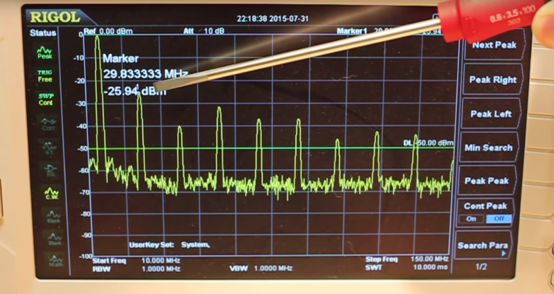
Having spent only $100USD for the MHS-5200A, [Craig]’s adventure is a complete teardown and analysis of the function generator. While it sort of lives up to its specs, it’s pretty clear that some design decisions resulted in suboptimal performance. At higher frequencies and higher amplitudes, the sine wave output took on a markedly non-sinusoidal character, approaching more of a triangle waveform. The spectrum analyzer told the tale of multiple harmonics across the spectrum. With a reverse-engineered schematic in hand, he traced the signal generation and conditioning circuits and finally nailed the culprit – an AD812 op-amp used as the final amplifier. An in-depth discussion of slew rate follows in part 2, and part 3 covers replacement of the dodgy chip with a better selection that improves the output signal. We’re also treated to improvements to a low-pass filter that fixed a nasty overshoot and ringing problem with the unit’s square wave function.
If hacking the MHS-5200A seems a bit familiar to you, that’s because we covered another reverse-engineering exploit of it recently. That hack of the serial protocol of the instrument was by [WD5GNR], also known as Hackaday’s own [Al Williams]. Cheers to both [Craig] and [Al] for showing us what you can do with a hundred bucks and a little know-how.


Quality Chinese Engineering, or…what did you expect for $100?
Educational, I guess.
You shouldn’t do that. You’re hacking it to get more/better functionality out of it than the manufacturer intended. You should simply pay more if you want more…. ;-)
I have the parts on order to make the same changes. I did order 0603 parts to match the original instead of the smaller parts in his BOM except for the very small capacitor which was out of stock in 0603. As cheap as they are, I suggest ordering more than the two you need to avoid losing one or two during handling (plus, that’s how your junkbox gets stocked).
Thanks for the mention Dan!
Yes, always get extras. Nothing like squeezing an 0603 a bit too hard with the tweezers and having it suddenly exit reality as we know it.
Especially certain resistors. Sure you can get the 10 you need for $1, but you could get 1000 for $2.
Woo! I enjoyed that, thanks
I’m curious if the AD chips are legitimate. Knowing Analog’s history with Chinese manufacturers, I would *not* be surprised to hear that they’re clones. Not that it makes the replacement with a proper TI chip (which was, even comparing datasheets, much better for the task) is any less legitimate nor any less valid.
Anyone willing to find out… for science?
In the first video I did replicate the circuits for both the AD chips using parts straight from Digikey with identical results. Although I didn’t show it in the video, I did go as far as to replace the AD chips on the board with ones from Digikey, with no effect.
If they are clones, they are functioning identically to the real thing (in this circuit at least).
I have the same generator MHS 5200A 25 MHz and is visible at 1 MHz the overschot and ringing!
the same effect is visible with scope tectronik 50 MHz after and before the elliptic filter!
Is possible that this effect not depend from filter?
I have simulate the besser filter on the article with 1MHz square signal with microcap 10 (eval.)
and is visible the same effect!!
Only if input impedance (e.g. 91 ohm) added in series to input signal and the same resistance is connected
to load this effect is not present (at 1MHz), but the amplitude at the output is half that input!
I suppose that the problem is the input impedence and I want try to adder a 50 ohm resistor in series before the filter
cutting a track!!
Interesting, I once designed a function generator and ended up designing my own variable gain amplifier and output stage due to the limitations that are evident in this unit. Very hard to keep the output flat at high frequencies, do you know if the more expensive generators include some kind of equalization to compensate for gain/phase errors?
I’d be interested in reverse engineering the uC to FPGA communication. I’m sure you could add a lot of features if you could roll your own firmware.
I am curious, what version of the unit did he have? They come specified from having a maximum frequency of 6 to 25MHZ (all the same part number of course). It seems likely that the difference is just the perormance of th e output amp seeing as they all seem to have the exact same firmware/etc
It could be just a firmware difference or at best the LPF that was replaced has a lower cutoff in the cheaper version. It would be nice to know.
I have the 25MHz version. While I haven’t looked at the lower frequency versions, others have noted that they appear the same from a hardware perspective; my guess is that Darren is right and it’s probably just a firmware difference.
Just for laughs I would like to see a proper phase noise characterisation of this POS.
I have just got my 5200A yesterday and, overall, I am very pleased with it. The output filter/amp modifications will be made shortly.
My primary intended use for the 5200 is as a RF signal generator with modulated tones.
As a complete ‘Newby’ to this product and function generators, I am having, not unexpectedly, problems setting up software to create my own ARB waveforms.
I managed to create a modulated waveform, using the software supplied with the unit, and save it to a .csv file but I cannot use this file to output this shape from the 5200.
ANY help would be appreciated!!
really , the software that comes with the unit is too weak.
However if you use Linux , you have a way I found this site to generate arbitrary waves and recording on the unit.
to the site’s tips worked perfectly for me.
the tip is this site
https://github.com/wd5gnr/mhs5200a
if you want I make a video explaining how to transfer to the unit waveforms
sorry my english wrong, I am using a translator .
hugs
Rodrigo Hernandes
FYI: I translated the chinese manual from CD by google – it contains communication protocol specification
Here’s a little update. Needed the arbitrary function generator and I have no Windows machine in the house. So, wrote a little ditty to upload arbitrary functions to this device and send commands. Enjoy! https://github.com/kpishere/mhs52xxA
Anyone know if the procedure to replace the OpAmp is still posted anywhere ? The links in the article seem to be dead, I guess since it was 10 years ago. 🙄