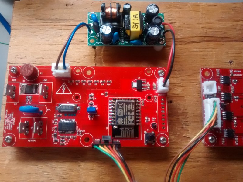
Building your own hardware to measure AC power isn’t a simple task. There’s a number of things to measure, including voltage, current, power, and power factor. The Atmel 90E24 is a single chip solution designed for this exact purpose. Connect a few components, and all the power data is available to a microcontroller over SPI.
[hwstar] built a custom power monitoring board based on this IC. His AC-Emeter will give you all the measurements you’d want, and includes an ESP12 module for data collection and WiFi connectivity. Aside from the Atmel 90E24 device, a high power and low resistance resistor is needed for shunt sense current measurement. An external module is used to convert mains voltage down to 5V to power the board.
Of course, working with mains voltages can be a dangerous endeavour. Fortunately, [hwstar] provides some tips on how to prevent “equipment from being BLOWN UP” along with the open source hardware and firmware.
[via Embedded Lab]


He is quite right about using an isolation transformer to protect the equipment, but additional protection can be had using GFCI’s to protect YOU. This also provides a little additional protection for equipment, but GFCI’s react too slowly to protect most electronics.
I like the project, but think he missed on a few things. One is the possibility to use a current transformer or hall effect current sense IC to provide isolation with minimal loss of accuracy.
He really should have also used optoisolation on the USB lines, with the host side powered by the host, the board side powered by the board. If there needs to be a warning that the USB connector is at line potential, then I don’t think I would recommend that the project be duplicated.
I am the creator of this project.
I have a separate project for doing just that. It’s an isolated serial port. You can’t debug such a project without it.
Please see https://github.com/hwstar/ISO-port for details.
I never intended for this to be a non-invasive way of monitoring an AC appliance. I chose resistive measurement because it is inexpensive. (Hall-effect sensors and current transformers are more expensive than shunt resistors),
and may you may have non-linearity and phase issues to deal with.
GFCI’s are useless when you are connected to an isolation transformer, as the line and neutral leads are floating from ground. A GFCI is always a good idea when this is connected without an isolation transformer.
This board would benefit from labels on the TTL pins. I’d put them on the bottom silk screen since the top side connector will obscure them.
And then I saw it: the legend clearly marked on the top.
I did the same using earlier ESP module, cellphone charger and chinese ($12) power meter (the one covered here some time ago). Not the most economical thing in the world (esp = constant ~1W).
The Atmel site says these are only available in the US. That’s a pain for those of us on the other side of the Atlantic.
I am the creator of this prject
The 90E24 is available from Mouser. I don’t know why you couldn’t order it from them.
For some reason I think the design of that PCB is wrong. For one thing there should be nothing in front of the wifi antenna, and it should be free of ground plans under it. There are ground plans all around it and a big connector right in front of it. That will just reduce the range of that module and lowers the speed of the communication as the dsp inside the wifi-module has to keep re-transmitting the not-acknowledged data over and over again.
plane*
The ground plane is removed underneath the antenna on both sides of the pcb. The connector can be removed once the unit is programmed as it is just a programming connector.
But the pin headers and the pads still remain on the board even if you disconnect the connector.
How much clearance around the antenna would be acceptable?
I have not seen any issues during testing with speed or evidence of retries. The data rate is limited anyway as the 90E24 chip is a slow SPI peripheral.
Hi Steve,
You won’t see any issues as the wifi-module have a DSP inside of the to take care of the reflation issues, if you really want to see the issue you need a sniffer and wireshark. You are correct about the data rate, considering the low data rate it will work just fine. I’m not trying to attack your project, on the other hand I believe it’s a really useful device. I’m just trying to hint out something that I have experience on so you can improve it :) Usually 5mm is the recommended clearance around the module by the manufactures, but based on our (I work at a company with RF_Based products) experience it will be much better of you could leave the front portion of the module (antenna) on the edge of the board with out any components surrounding it. Just a comment!
Thanks for the tip. I’ll move the connector away from the front and move the board to the edge in a future revision.
I have released the revision A board blank which incorporates the rework on my Github site. This addresses all issues except the one pointed out above with the programming connector.