Control systems are exactly what you think they are: systems designed to control something. Perhaps a better way to put it is systems design control the behavior of something. The term “control systems” does an excellent job of being vague and most of us (originally) don’t think too much about it until its brought to our attention or we crash a robotic armature into itself and investigate how that horrifying event was allowed to happened. Usually during this investigation our internal dialog has a loop running that goes something like: “why the hell will the system allow me to manipulate it in a self-destructive way!?!”
What I found was my own ignorance, I hadn’t implemented a proper control system. One could make a case claiming that I hadn’t taken ANY control system into account whatsoever. I jumped in too deep, too fast (sound familiar?) and paid the price of crashing a rotating arm into another part of the system. Luckily, a friend stepped in and repaired the arm for me and metaphorically pointed to a large neon sign on the wall and said “you can’t ignore this”. He walked over to pull the chain dangling beneath the sign, the high voltage energized the gas in the tubes blinding me with the now unavoidably obvious words: Control Systems.
Evidence of Control Systems
There is evidence of control systems all around us, we use them all day without giving them any thought. I get up in the middle of the night in a daze, I shuffle down the hallway like a zombie for a glass of water and I never miss the handle of the cupboard with my outstretched arm. I swing open the door to the cabinet the appropriate distance without any problems and grasp a glass with my other hand. I do these things without actively focusing on them but nevertheless, these are control systems. I don’t squeeze the glass until it shatters in my hand as I grab it from the cupboard. I also have the ability to turn on the water from the faucet, fill the glass, turn the water off, and the only thing wet is the inside of the glass, not my hand or even the sink basin below the water faucet. This is an example of many complex control systems working towards a glass of water.
Rockets ignite and propel satellites into earth’s orbit, an elevator delivers us to the desired floor, control systems are everywhere. They have been around since forever and can be seen in some of our STEM forefathers’ (I think I just coined that phrase) most notable work.
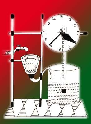
300 B.C. the Greek mathematician and inventor Ktesibios creates a water clock that uses a control system with water as an input and time as an output. Everything in between water and time is the control system.
Improving on previous windmill designs, in 1809 William Cubitt created windmill sails with automatic shutters that were adjusted by wind-speed and a counterweight, this is a control system. Wind is the input and constant rotational energy is the output.

To observe an existing system and point at the input and output stating “water in, time out, everything in between them is a control system” doesn’t explain how a control system works or is designed but we’re getting there. These inventions require some fairly complex mathematics and we’ll get to that in a subsequent article but for now we’re laying a base of understanding. We have looked at a few examples of control systems in nature and a few man-made control systems. I shared my ignorance of control systems and then tried to redeem myself by telling you that I can fill a glass of water.
We will also have a look at some block diagrams and I should warn you that at some point we’ll encounter some mathematics you’ll never want to see again. Luckily the first thing we’ll do when we see these dreadful maths is devise a plan to get the hell outta there. Once we are safely out of harms way we will take care of some simpler operations i.e. we’ll do a bit of algebra instead of calculus and differential equations. Now come with me, friend, for after the break the real fun begins.
The Block Diagram
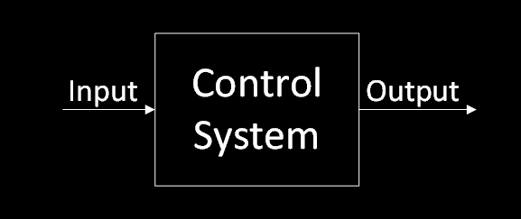
For our purposes I have drawn up an oversimplified version of a single input, single output (SISO) control systems. The block diagram is the control system. We can manipulate it with algebra and introduce new components as needed to get the desired output. We will however quickly replace these generic labels with labels that better describe the elements of the system. We will also break the “Control System” block into multiple blocks that make up the system. You can think of this diagram as the high level description you would give to a child, remember “water in, time out, everything in between them is a control system”. The next bit is a little more detailed yet still symbolic in that we aren’t looking at the mathematical components of each block quite yet.
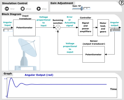
Lets create an example of a specific control system we hypothetically want to design. How about a large satellite dish? Good, its done. So we have a large satellite dish that is rotated by a geared motor. The desired position of the dish is input with a potentiometer which the controller uses to determine the magnitude and direction of required movement to achieve desired output. Also taken into account is the motor itself, the load we are moving (large satellite dish), and the gearing required to do so. The output of this system should be fed back to the input by something called (wait for it), feedback. The feedback path contains a second potentiometer that is adjusted as the dish rotates and goes into a summing junction with the input.
We can now draw a new block diagram to represent the more detailed description of what we have going on in this system.
We have discussed the function blocks and the basic flow of the system, let’s have a look at the signals, which are in blue in the above diagram. The initial angular input is an angle which the potentiometer (Input Transducer) converts into a voltage. At the summing junction there are two signals coming in and one going out, the two coming in are the voltage proportional to input and voltage proportional to output. If you notice the polarity markings on the input signals we have the input minus the output which results in the error signal. The angular output is in fact an angle that corresponds to the direction that the dish is pointing. In order to use the angle in our control system the potentiometer on the right (Output Transducer) converts that angle to a voltage that is sent to the summing junction. That junction is responsible for comparing the user control, and making sure action is taken until the actual position matches it.
Modifying The System
If we know that the behavior of the system is to drive the error signal to zero then we have two ways to measure the output of the system. Transient response and steady state error can both be measured to analyze the outcome of our control system and modify it accordingly.
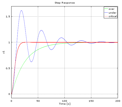
Transient response is the signal’s reaction to a change in the system, which can be seen in the Step Response plot to the right. There are 3 types of transients which can be classified by the type of damping ratio used: over-damped, under-damped, and critically damped. The goal being a response as close to critically damped as possible.
We can visualize the importance of both the transient and the steady state error if we look at the plot response as a representation of an elevator going from the basement to the first floor. The under-damped oscillation is obviously going to be a problem and possibly cause some uneasy stomachs along the way as the speeding elevator overshoots the floor and overcompensates in the opposite direction, repeatedly. The over-damped elevator will get us there in a very smooth fashion, eventually. The critically damped response is shown in red and defined to be the fastest settling signal without oscillation.
In regards to the robotic arm that I crashed and wondered why this was possible, we can see one answer to that question in the step response plot. It’s possible that I was controlling an under-damped system and the arm crashed in the overshoot of the first half cycle of oscillation as seen by the blue line in the plot.
In this example there is not any steady state error introduced. Steady state error in the elevator scenario would result in the elevator doors opening somewhere between floors 1 and 2. Had this been the case we would deal with the steady state error by changing our controller so that the doors open at floor 1.
Clicking the antenna simulation screenshot to the left will take you to the interactive simulator in a new tab (requires flash). You can play with the value of the gain to see how it changes the output response. Hint: you have to hit the rewind button to start a new simulation.
Transfer Function
A transfer function is similar in concept to the gain of a system and is defined as the ratio of output to input. We use the term transfer function instead of gain in reference to a control system as it implies the use of the s-domain (I realize that I have not introduced what the hell an “s-domain” is but lets overlook this for now as it will be explained in a separate article) to get a desired response from a system.
The block diagram as we have drawn it contains a lot of information about the control system, the main thing it lacks is the maths required to model the system. The transfer function is where the math could be found and in our system is the combination of the controller (math) and the plant (more math).
Controller & Plant
The controller contains the mathematical models of amplifiers for the signals and the power to drive the large motor. The plant contains mathematical models that represent the specs of our motor which would be readily available in a real world situation and include things such as the motor’s RPM at a certain voltage, and the resistance of the motor. We would also need information about the gear ratio between the motor and the satellite (this is a mechanical amplifier). The motor will have a mechanical load during operation and we can predict what this will be with an equivalent mechanical load equation which uses: equivalent viscous damping of the load, and the equivalent load inertia. In keeping with our math-less theme of this introduction we’ll skip what that means mathematically for now.
Final Thoughts
The intent of this article is to shed some light on what control systems are and a basic idea of how they work. I think control systems are interesting and exciting in that we can calculate some of the variables to use in complex systems rather than take wild guesses at non-trivial unknowns (which used to be my jam).
We, as hackers and engineers learn on a curve as does the rest of the population and just like everyone else we sometimes reach a plateau in our ability to make the improvements on our own designs. I think a basic understanding of control systems could help a lot of us get through this slump. I will attempt to do you the same favor my friend did for me in opening my eyes to what a control system is, how to analyze what is going on in a system, and we will all get a little better at designing our own systems along the way.
What To Expect Next Time
In the next edition of Beyond Control we will look at some examples of electrical systems in the time domain. We’ll talk about their transfer functions in the s-domain, why we need the s-domain, and what it takes to go from the time domain to the s-domain (and back). That’s two sentences of me saying math, without saying math. See you next time!


I really like this kind of article that we’ve been seeing more of recently on HAD. Thanks!
You’re welcome Jason.
Glad you like it/them.
I’ve done all the crazy control stuff in my EE course, but this is the best intro to control systems I’ve seen. Great Job!!
I’ll +1 that. While it’s great to see what people have been building, it’s also really useful for those of us with non-hardware background (programming in my case) to learn some of the theory from pros.
If you want to know more about tuning, I wrote this article for Circuit Cellar Ink in 2000 (Oh cripes!!! 15 years ago already?)
http://bobodyne.com/web-docs/robots/PIC-SERVO/Kilian120.pdf
I would like to see some coverage on manual and auto-tuning as a lot of the time in real life you don’t get the luxury of having a system level model (or that the system can change) and you ended up having to tune the control variables.
tekkieneet,
Stay tuned (see what I did there?) for the next article, I think it is headed in that general direction.
Do you plan to cover more than Ziegler-Nichols PID tuning, or is it a more general overview?
Well, we all know how REO Speedwagon would respond to that! :-)
As a college student who was actively terrorized with Control theory these past few semesters, I can say that this article is very well written, and indeed i was awed by the ammount of control theory used everywhere, especially in analog electronics.
Excellent intro to control systems, Brandon. I’m glad to see content like this on hackaday :) Looking forward to the next one. I’ll be adding this series to my reference material library!
For those looking for additional material on control systems, here are my two favorites:
Beginners/Refresher:
I’ve been using Brian Douglas’s Control System Lectures ( https://www.youtube.com/channel/UCq0imsn84ShAe9PBOFnoIrg ) as a refresher for a while now, but I think great for beginners. Really well produced.
Pro/2 Legit 2 Quit:
Highly recommend the textbook Control Systems Engineering by Norman Nise (expensive, but worth every penny imo):
http://www.amazon.com/Control-Systems-Engineering-Norman-Nise/dp/1118170512/ref=la_B001H6N2G0_1_1?s=books&ie=UTF8&qid=1449081799&sr=1-1
I am an EE undergrad in my sophmore year. Now, the way I understand it, control theory is taught after Signals/Systems. Now, I haven’t even taken Diff Equations yet(but will be next semester). I am really interested in Control Theory and the like. If I wanted to get a jump on it, would getting the Norman Nise book be a bad idea? As in, it would be too over my head with my current lack of classes. I do, watch Brain Douglas’s videos, but sometimes they are not quite detailed enough, and so I don’t fully grasp it.
If you’re interested in getting into the details of control theory, I’d recommend getting the book. It does a fantastic job diving into the subject, very readable, builds on itself, good examples, etc.
However, I’d check your universities control systems professor/syllabus to make sure you don’t buy the wrong edition (that is.. if your university uses this book). Heck, by the time you take the course there will likely be a new edition.
Gain in this simulation is specifically within the control block. It is not the same as the transfer function of the entire system. It would be better to just refer to PID controllers and say gain is equivalent to the P from PID. (Proportional feedback)
“The goal being a response as close to critically damped as possible.”
I think this way of teaching damping factor has confused generations of controls practitioners. Rarely is critically damped exactly what you want. Lots of people want a system to get to a “good enough” position as fast as possible. In that case, a little under damped system is good (fast). Some others can’t overshoot and must be conservative about never allowing it, even with a little unknown variance in the system. In that case, over damped is better. Others are very concerned with stability margin, which usually means over damped is better.
I think that sentence is one of those things that has been repeated so many times people don’t even think about what they are saying. In fact, the author makes the case for under and over damped systems being valid just after he says critically damped is the goal.
If you’re worried about “reasonable behavior” more than “optimum speed” overdamping is the way to go. Tweaking the algorithm until it’s critical is ok but has downsides when overshoot / instability is a problem. It’s also ok sometimes to just buy a bigger motor.
(Small home robotics experiements are my forté, not industrial robotics, so don’t listen to me if your boss says that his assembly line needs to run faster.)
Awesome article! Stoked for the next one.
Something that can be done if you want a fast response and still good control would be to think of it in stages. First you leave the system in open loop and send your output high and move into a predetermined range where you close the loop and kick the PID controls in. For example, lets say we’re trying to fill a tank with water. You have a pump(your motor or output) that you can control speed with to bring water to the tank. You would have a level feedback ranging from 0 -100% full.
Your potentiometer input is a set point and let’s assume we want to fill the tank half full 50%. In this example, you may want to ignore the level feedback in terms of generating a error signal(open loop controls) until you’re 35% full and then at that point start controlling with the error signal (closed loop system) By doing this, you can tune your control loop tighter where you need the control…
As for where you start close your control loop that will depend on your system. If you need super tight controls you may not be able to do a staggered approach like this at all.
It’s still closed-loop control from the start, since you measure the output and use it to produce a control signal. There are different ways to cope with system saturations: gain scheduling, cascade control, anti-reset windup…
Critical damping never survives contact with manufacturing anyways, so if you need it to be at the critical point you are all ready in trouble.
An improvement to HAD-articles could be a list for further reading. Ofc I can google the subject, but I’m sure the writer got a favorite book. Also, keep calm and make sure your poles are in the left half plane!
Understand that “large satellite dish” is relative term. I still have C band dish mounted on it’s post. I don’t believe it has anything that monitors it’s actually monitors the dish position and sending feedback to a controller. I believe it’s control system remembers where it’s currently at and know how to get to programmed positions by monitoring the motor rotation direction and number of turn the motor in the linear actuator makes and the controller shows where it’s supposed to be. Just like radio receiver tuning dials display what the tune frequency is supposed to be , even the digital displays
That’s known as open-loop control. The block diagram shown in the article would just have that feedback loop cut. Open-loop systems can sometimes be desirable (achieves 0 steady state error), but are not robust to unknown influences on the system (what if wind blows the dish one way, or if the gears a worn down and the system rotates faster in one direction than the other?).
Steady-state error rejection is much easier to obtain in closed loop, precisely because of imperfect modelling and perturbations. It’s implemented with an integrator (the “I” of PID controllers, unless it’s already present in the system).
May I suggest, for the second article, that you keep “dreadful maths” and its relatives critically damped? :)
You Ninny, it is “Math”, not “Maths”. Ref: http://m.youtube.com/watch?v=SbZCECvoaTA
Really? You are correcting the quote from the article?
Here is a great article that talks about PID control for a line following robot. I used this article to teach 5th-8th graders the basics of PID control so they could build a Lego Mindstorms robot for the First Lego League challenge. It makes the whole concept pretty straight forward and easy.
http://www.inpharmix.com/jps/PID_Controller_For_Lego_Mindstorms_Robots.html
The flash demonstration is not behaving as I’d expect. -0.136 overshoots mildly, about the same as -0.04 say. But if I enter -0.137, it is very underdamped.
“why the hell will the system allow me to manipulate it in a self-destructive way!?!”
Because the person(s) who designed it failed to account for people (everyone who didn’t design it) not having intimate knowledge of how the thing is supposed to work, especially what *not* to do with it.
One non-disastrous example, the original iPhone 4 antenna. The people who designed it knew not to bridge the antenna gap with a fingertip. Unfortunately they put the gap precisely where most right handed people would rest the tip of their little finger. It was worse for southpaws. Can’t shift the part of the palm at the base of the thumb. Simply placing the gap at the top or bottom end of the phone would have eliminated the issue.
Here’s another one which if you’ve worked in a restaurant that has a soft ice cream machine you may have encountered. Older machines have completely independent freeze and stir systems. You ALWAYS turn on the stir switch before turning on the freeze switch. NEVER turn on the freeze switch alone. Naturally this leads to people turning on the freeze and forgetting to turn on the stir, then realizing they forgot a few minutes later. They turn on the stir and *chunkcrunkgrunch* the machine is broken. There is NO EXCUSE for those to be made that way. It doesn’t even require any electronic components. A simple interconnected arrangement of two switches* will ensure that power to one system cannot be turned on unless the switch to a prerequisite system is turned on first. Is it laziness or simple ignorance by the people who design these systems? Or is it calculated mercenary maliciousness, knowing that a certain percentage of people will forget the correct procedure and damage things – which results in a need for expensive repairs?
Then there’s the “grand poobah” of control system design failure, the Therac 25.
*A double pole switch for the stir with one half of the switch in series to a single pole which turns on the freeze. Dead simple and screw-up proof. Stir switch off = freeze does *not* work. If you must switch both lines for AC, use a QPST and a DPST. Or even simpler, a QPDT with one way doing Stir+Freeze and the other Stir only.
Indeed. Any robot arm can and definitely should be designed in a way that prevents crashes into itself – having limit switches on a CNC mill to prevent it from _being able_ to go off the rails is the simplest possible example; a bit of math can do the exact same thing even for intricately articulated robot arms; one should never try to directly control its motors directly. Failing to prevent this sort of thing is just negligent and poor design.
even the most advanced robot arms STILL have limit switches on top of calculating travel distance, just in case one or the other fails.
Introduction to Control course :
https://www.youtube.com/watch?v=gJzY6jOcgN0&list=PLmK1EnKxphikZ4mmCz2NccSnHZb7v1wV-
+ already mentioned Brian Douglas has a great collection of control theory videos on YT
My official job title is “Systems Control Technician”, but I don’t ever tell people that … it’s too hard to explain. I just say I fix electronic stuff in a factory to keep production running. The diverse production plant has controllers ranging from vintage (1960’s) to hi-tech electronic controls, robotics, PLC’s and fuzzy logic. The tuned process loops are ever-changing by the hour, whether it’s temperature changes, mechanical wear, sticky valves, or a machine operator that doesn’t like what the value reads on the display. I’ll just ask them “what do you want it to read?”, or “it seems close enough, but I’ll check it” … and then I’ll walk away. A few hours later they thank me for tuning the controls even though all I did was sit down for a few minutes and drink a cup of coffee. In the classrooms and labs it’s all about precision and response … in the real world, it doesn’t matter much … “It’s close enough”.
Ha! That’s like some old machinist told me about the speed dials some models of LeBlond metal lathes had on top of their headstocks. When there was a newbie in the shop he’d go to a lathe that was making a cut, make like he was listening carefully to it, turn the dial a little then “listen” again and nod his head.
The dial does *nothing*. It’s merely a chart that suggests speeds for different metals and indicates how to set the gear levers on the headstock.
This article is a very good summary of the concepts presented in Norman Nise’s Control System Engineering (https://books.google.com/books/about/Control_Systems_Engineering.html?id=-qkeAQAAIAAJ&source=kp_cover&hl=en). Most of us had to read this in our undergrad Engineering, wherein the satellite example is a running system example throughout the book. A very good book for those of you interested in taking this deep into the weeds :).
Brandon, you should point this yt channel to the HAD community in your next article. It will come in handy. It’s all about s-domain control stuff. Really good material. https://www.youtube.com/user/ControlLectures
Nice article, but the blue on black is pretty hard to read in the diagrams. Any color with better contrast would be an improvement for future posts.
It’s interesting that you talked about how control systems can be used to modify signals. I have been thinking about working with control systems when I graduate. It would be smart to use system control because it could help you find problems that need to change.