If you’ve ever worked on old gear, you probably know that electrolytic capacitors are prone to failure. [Dexter] undertook a repair of some four-decade-old capacitors in a power supply. He didn’t replace them. He fixed the actual capacitors.
The reason these units are prone to fail is the flip side of what people like about electrolytics: high capacitance in a small package. In a classic parallel plate capacitor, the capacity goes up as the distance between the plates shrinks. In an electrolytic, one plate is a rolled up spiral. The other plate is conductive fluid. The insulator between (the dielectric) is a very thin layer of oxide that forms on the spiral. Over time, the oxide degrades, but this degradation repairs itself when using the capacitor. If the capacitor isn’t powered up for an extended period, the oxide will degrade beyond the point of self-repair.
The manufacturer forms the oxide layer by careful application of a forming voltage into the freshly-made capacitor. This not only creates the dielectric layer but also sets the expected current direction. It is possible, at least sometimes, to use the same technique to regrow the oxide and bring a capacitor back to life. That’s what [Dexter] did, using a current-limiting power supply to prevent damaging the capacitor during the regrowth.
We have covered homebrew capacitor construction a few times before. [Dexter] isn’t sure he trusts the forty-something capacitors over the long haul, but they did seem to repair adequately. The video below shows a different reformation project, this one fixing a video camera from the 1960s.


Reforming electrolytic capacitors has been standard practice when restoring or even just taking devices of storage for decades. However the video is quite a good introduction for people who assume that once the capacitor has lost a bit of capacitance that it’s the end of the line. I’ve successfully reformed capacitors in 1930s radios with no issues – it’s the wax coated paper lower value capacitors that you generally have to replace in vintage electronics, as they simply dry out and can’t be revived.
+1 Yep. Stored variable frequency drives not using film capacitors have to go through this, or they usually go bang as soon as you turn them on.
This works sometimes, sometimes the cap is just dried out and they are toast. It’s worth a try though. I did a similar thing with the big cap bank on my yag laser, it has dozens of 450v caps for the flash lamps and they hadn’t been powered up in probably 15 years so I set up a 385v power supply and some current limiting resistor to slowly charge the bank up. It seems to have worked, the power supply worked when I eventually went to power it up for real.
He’s using a power supply in current limit mode to reform these caps. An easier and cheaper solution is to desolder the positive terminal of the capacitor. Then connect a 250 KOhm resistor in series with your power supply and switch it on. When the capacitor is fully deformed, the voltage on the capacitor will be close to zero initially, but gradually it will climb as the capacitor is slowly formed.
Of course you have to select a resistor with the right voltage and power rating, as initially the resistor has the full voltage over it.
For instance, for a 240 VAC bridge rectified voltage, this yields to 336 Vpeak. Then the resistor has to be V^2/R = 0.45 W (make this 1W), and the resistor has to be able to withstand at least this. 200 VDC rated resistors are more common, so you can put two of these in series (they have to be the same value of course).
Another trick (less safe) is to prepare a special power cable: attach a light bulb between your power socket and the device. When excessive current flows into the capacitor, the light bulb will limit that current. For instance, a 40 W bulb.
http://www.angelfire.com/electronic/funwithtubes/steps_to_first_power_on.html
Whatever happens, listen very closely for hissing or a foul acidic smell when turning on an old device and immediately switch it off. That’s likely to be electrolitic gas escaping from the electrolytic capacitor.
‘Lamp Limiters’ are an essential tool for anyone restoring vintage electronics. Does need to be a filament bulb though obviously! I’ve got quite good at estimating the current draw of a radio based on the brightness of the lamp.
100W lamps are also usefull when tracking down bad diodes in a motor controller:
http://www.wolftronix.com/amc230_514/
That was actually a good troubleshooting read.
…I had no idea you could do that….
Nice to learn something completely new.
^ This.
This is why articles like this are so important. It doesn’t matter that some of the commenters (myself included) know all about this, at least one person has learned something new and that is invaluable.
Interestingly, I am currently working on building a capacitor leakage tester/reformer.
Hah, was wondering how long it’d be ’till you saw this one… And, agreed with you both, I had no idea, and timely.
Find it interesting because in our company we are building controls for old papermachines. From time to time we get an old frequency converter or VFD in Germany we call them FU. Before they can get reused they where powered up starting with 50V AC 3Ph and increasing it over 5h to 400V. They could reactivate drives that where 5-10years unpowered and its cheaper to try this before because these drivers cost around 2000-10000$ new.
“In an electrolytic, one plate is a rolled up spiral. The other plate is conductive fluid. ”
Nope. In electrolytic capacitors *both* plates are rolled up conductive spirals. In between the spirals we have the dielectric which can be of different materials. Electrolytic capacitors use paper impregnated with the electrolyte.
Imagine two foils of kitchen aluminium with one foil of plastic in between, just wind them onto something paying attention not to make the two foils touch each other then attach wires to both aluminium foils and you get a capacitor. Now if you do the same using paper in place of plastic and the right electrolyte solution you get an electrolytic capacitor.
You are correct in terms of the physical construction, but for an electrolytic capacitor the operation is different. The paper layer is soaked with a conductive electrolyte solution, and the dialectic is actually a thin oxide layer on the foil. Your description would be correct for a paper/oil capacitor which has a few orders of magnitude less capacitance than an electrolytic capacitor due to the different operational principals.
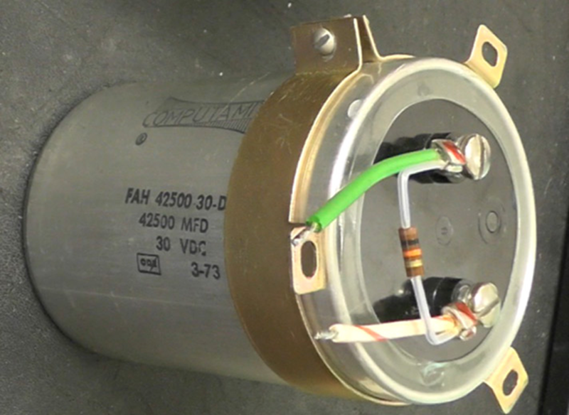
The author stated he probably wouldn’t want to use a 40-some year old reformed capacitor long-term, but I’ve had good results with reforming high-quality electrolytics and using them long term. Beware of electrolytic capacitors that appear to have leaked some of their filling — on larger ones like the unit pictured in the article, you’ll usually find some crust around the vent plug on the terminal end if they’ve been overheated and started venting/leaking.
Not exactly a scientific statement, but I’ve found that the heavier the electrolytic (weight-wise), the higher the quality and the better your luck will be at reforming. Anyone who has handled good brands (Mallory, Sprague, CDE) and lesser no-names of the same physical size/capacity/voltage will quickly pick up on which ones are the “light” brands!
I have a box with 10 big/old capacitors (Sprauge Powerlytic 36D9175 120000 – 15DC 7743L) what would be the best way to test them? I kept them around to make a capacitive discharge resistance welder but would like to make sure they are good/safe first
from what ive heard,
you miiight want to use goggles or glasses while restoring capacitors,
as sometimes they refuse to reform in a dangerous/messy way…
ive also heard that if the capacitance measures 1.5x or more of its rated value it IS too good to be true, and may fail soon
+1 some hearing protection and clean underwear is also recommended.
Use a proper series resistor when reforming and one will never blow up. As the resistance of a failed cap goes down power dissipated by the series resistor will go up.