There are a few classic video games that rely on vector graphics and special monitors. Asteroids is incomplete if you’re not playing it in its original arcade format. The same goes with Tempest, Lunar Lander, and the 1983 Star Wars arcade game. Emulation of these games is possible, even with MAME, but the display – like every display you can buy today – is still rasterized. The solution to this problem is to create a vector display output for MAME that works in conjunction with adapter boards and DACs connected to a monitor.
For this year’s Chaos Computer Congress, that’s exactly what [Trammell Hudson] and [Adelle Lin] did. They’ve created an open source vector gaming system that connects MAME to XY monitors and oscilloscopes.
The build uses a custom board equipped with a Teensy 3.1 microcontroller and a 12-bit DAC to convert XY coordinates sent by MAME to vectors that can be displayed on any XY monitor. This, of course, requires a patch to MAME, which the maintainers rejected as being an, “unacceptably hacky way to achieve the intended result.” It does achieve the intended result, though: allowing dozens of vector games playable on whatever monitor supports vector graphics.
So far, [Trammell] and [Adelle] have gotten their system working on Vectrex consoles, analog oscilloscopes set to XY mode, and vectorscopes that litter every broadcast station and surplus shop. Check out [Trammell] and [Adelle]’s talk, and if you want to build the V.st vector display driver, the board is available from OSHPark.


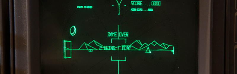
Looks like Battlezone. And I have a Tek x-y display! Gotta get the board!!!!!!
Oh yeah. Proper tank driving handles. Hmmm.
this is a fun hack but honestly, i dont think you are going to get a much higher quality image than on a 4K display. rasterized versus vector graphics is the analog vs digital argument all over again.
And since film is better than digital capture it just illustrates how this hack is awesome, must be done and rocks
Next we’ll have people listening to music on vinyl again.
We already do have people all over the world listening to music on vinyl again (or rather still), and it’s awesome!! (of course you need a turntable with light tracking weight – say 1.5 to 3 grams, not a “record player” (ha ha) with a brick and a nail gouging our your grooves. Especially not one that “converts” your vinyls to USB
I know, it was an example of other stuff people like to do for fun, even though the quality is worse than modern digital alternatives.
If you’ve been here longer than a few months, you should know better than to start the “vinyl quality is worse than digital” thing…
…sheesh…
Again?
Will someone please revive LASER MAME?
You ought to be able to feed the analog signals out of this board into a galvo drive amp and use the Z output to control the current on a DPSS laser module.
The two attempts I know of were abandoned before having all the bugs worked out. They didn’t have fast enough galvos so there was plenty of flicker, rounded corners and other distortions due to lag. With fast enough mechanicals, the next step would be curvature compensation. The images on the original monitors looked right because the screen curve closely matched the beam radius.
Project that onto a flat screen and there will be some distortion. Dunno if it would be enough to be distracting or noticeable at all.
Color vector scan games like Tempest and TAC SCAN would be a mite difficult with lasers. Three separate sets of galvos for red, green and blue lasers, converging them all and setting up an exact distance from a screen would not be fun. Perhaps Open CV and a self convergence grid projection?
well a lot easier would be to control mirrors with the servos and use a prism for combining the color beams. here is an old eg: http://hackaday.com/2011/11/10/rgb-laser-projector-is-a-jaw-dropping-build/
Oh, I never said it would work, the issue will always be the galvos, they are just not fast enough even with ultra low mass galvos and mirrors. I dont think there really is any way to do it mechanically.
For full color you would use a RGB laser system with one set of galvos, the reg, green, and blue beams are combined into one beam with dichroic mirrors and then bounced through the galvo set. This way there is no alignment issue. Most diode systems have analog control, though I dont know how the linearity of power would be, you might have to do some sort of calibration for white balance across the analog range.
Happily, there are several beam steering methods faster than galvos on the market and in development. The two that come to mind are 2-axis mems-mirrors and liquid-crystal deflectors. The Mems-mirrors I’ve seen get +-5 degrees of deflection and resonate north of 10KHz. The liquid crystal deflectors can go faster, but 2-axis designs are rare. Another solution to speed is just go parallel and divide up the draw list between a bunch of galvos. (alignment between the beams gets interesting though…)
In fact, Trammell submitted a pull request to our (the MAME team’s) github page. Unfortunately, it was more than a bit of a kludge, as it relied on OS-specific functionality but put that code into the core vector class rather than in the OS-dependent layer. As best I can tell, he’s apparently had better things to do than to rewrite his proposed change in a less hacky way.
Hmm. I have a Battlezone Electrohome monitor sitting in the corner, and schematics. You can see the radar and score burnt in to the CRT.
The screen is the least of your worries – it’s the same as a raster screen. The (vector drive) electronics and the drive coils on the neck of the screen are the difference.
Don’t throw it out – there are lost of people willing to part with money for a vector setup as they are getting very rare.
I’ve built this (on a breadboard). If you have an XY scope and just want to see something, all you need is a Teensy 3.1 and the MCP4922 DACs. You’ll have to use your scope x/y position controls and gain controls to try to center the display. The bipolar supply and op-amps allow the control voltages to swing negative, which makes it easier to center on a scope and is a must for magnetic deflection displays like the Vectrex.
Building the patched mame requires meeting dependencies for SDL2 and a few other things. It’s not terrible but it’s also not just a simple ‘apt-get’. On a 1.8 GHz core-M (Centrino) laptop it runs really slow – part of which I suspect comes from the fact that the patched mame still tries to render to the LCD.
So, there is still some work to do but it’s definitely cool. I am hoping Trammell will make it easier to have the code support intensity output while in ‘vectorscope’ mode. This will avoid the need for a ‘dwell’ position, which is hard to push offscreen without sacrificing some of the gameplay area.
One final thing is that at 12 bits of output, you’ll probably never see any stair-stepping, even on a large display. At 10 bits (as back in the old days), I can see how analog vector generators were helpful, as well as things like sine/cosine curve generators, but at 4096×4096 you just don’t see it.
You don’t see any at 6 or 8 bits. The DACs just output endpoints and the lines are continuous from integrators. Either the first fairly linear part of an RC, or a real op-amp.
I know this is an old thread but maybe you can help. I have been trying to email Trammell but he won’t respond. I just want to get a wiring diagram for the V.ST board and the breadboard version. For the V.ST, he states in his build of materials “Misc capacitors”, thats it….not which ones….not where they go… If you built the breadboard version, I would love to see your diagram. Thanks!! John
The schematics are available on Trammell’s website. They are Eagle CAD files. Install the free version of Eagle and you can open them. I don’t think there are any special timing caps, just bypass and filter types.
The lack of readily available large X-Y monitors leaves me on the fence on this one. I don’t want to have to play games on a small o-scope screen.
And especially on a digital storage scope, this would be rather disappointing.
Maybe it is worth some eBay and surplus shopping for the Tek X-Y displays that were used for computer terminals. They are the memory type with a charge plate and can be run in either mode – write and it stays without refresh for quite a while, or regular persistence.
Years ago I found a small 9″ XY display from some sort of audio testing equipment. It was probably for FFT freq response given what was on the overlay. HP made some 12″/13″/14″/17″/19″/21″ XY displays in their 13xx line. The 1338 was a 6″ RGB XY display.
You can re-wind the yoke on a regular B&W CRT and use an external XY driver board. You should be able to keep the existing HV circuitry if you attach the horizontal output to a similar inductance as the original deflection coil. You need about 300 KHz of bandwidth for your amplifiers. There are some ideas here: http://tubetime.us/?p=304 and http://hackaday.com/2014/09/18/building-a-vector-monitor-controller/
Of course, at this point it isn’t so easy to find large B&W CRT displays. Back in, say, 2000, you could easily and cheaply get 21″ workstation monitors. But there are still plenty of color CRTs, so maybe it’s best to go all-out and just do a conversion on a color set.
Hmmm,
Not so easy to do. You have to take the yoke off to rewind the deflection coils which means lots of color geometry adjustments when you put it back on OR just put up with the psychedelic colors – after all color CRT TV’s did come from the 60’s.
I was a TV tech for many years and I see this as a big (and dangerous) job.
So tell me, please, do you rewind both H and V Def coils of is the H Def OK at it’s 16KHz spec?
There’s an article here on hackaday about rewinding yokes. I think there the guy doing it builds an external HV supply, but I would at least give it a shot with the original HV supply, since it’s one less thing to build.
You are right, it’s going to be real work to convert a color raster display to vector. I wouldn’t attempt it myself. But B&W I think I can handle. It’s still pretty easy to find free 5″ B&W sets to practice on. Larger B&W monitors are probably getting rarer.
Well, as an experienced TV tech, this is a ‘doable thing’ but still more than I would be willing to take on.
Getting the horizontal drive to work with a different yoke would take extra inductors and some serious reactance matching – I doubt this path would be worth it.
The other path – redesigning the HT means that you have to also redesign the safety circuits that prevent the HT from going high enough that the CRT becomes an X-RAY emitter. We all know how dangerous that is.
Discontinued, but schematics are available on the site if you desire a vector MAME setup…
http://www.zektor.com/zvg/index.html
Unless they have released the code for the two microcontrollers you can’t roll your own ZVG.
I’ve posted slides and the text from our talk: https://trmm.net/Vector_games_32c3
The difference between playing vector games on a proper vector graphics monitor and any other type of display is huge. Defenetly not a vinyl verses digital argument. I sometimes make Vectrex games and even the best emulation is nothing like the same effect as loading it up on my real Vectrex.