Cheap, brushless motors may be the workhorses behind our RC planes and quadcopters these days, but we’ve never seen them in any application that requires low-speed precision. Why? Sadly, cheap brushless motors simply aren’t mechanically well-constructed enough to offer precise position control because they exhibit cogging torque, an unexpected motor characteristic that causes slight variations in the output torque that depend rotor position. Undaunted, [Matthew Piccoli] and the folks at UPenn’s ModLab have developed two approaches to compensate and minimize torque-ripple, essentially giving a cheap BLDC Motor comparable performance to it’s pricier cousins. What’s more, they’ve proven their algorithm works in hardware by building a doodling direct-drive robotic arm from brushless motors that can trace trajectories.
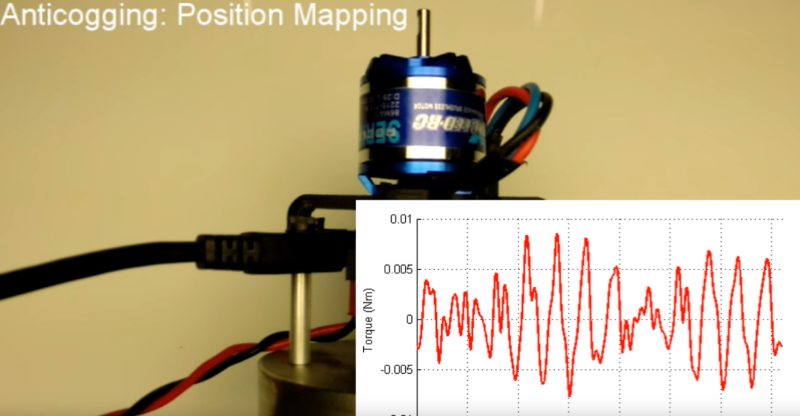
Cogging torque is a function of position. [Matthew’s] algorithm works by measuring the applied voltage (or current) needed to servo the rotor to each measurable encoder position in a full revolution. Cogging torque is directional, so this “motor fingerprint” needs to be taken in both directions. With these measured voltages (or currents) logged for all measurable positions, compensating for the cogging torque is just a matter of subtracting off that measured value at any given position while driving the motor. [Matthew] has graciously taken the trouble of detailing the subtleties in his paper (PDF), where he’s actually developed an additional acceleration-based method.
Hobby BLDC motors abound these days, and you might even have a few spares tucked away on the shelf. This algorithm, when applied on the motor controller electronics, can give us the chance to revisit those projects that mandate precise motor control with high torque–something we could only dream about if we could afford a few Maxon motors. If you’re new to BLDC Motor Control theory, check out a few projects of the past to get yourself up-and-running.


“cheap brushless motors simply aren’t mechanically well-constructed enough to offer precise position control”
Bull. The cogging torque has nothing to do with the quality of construction or materials used. These motors are designed for maximum torque at high speed. Not precise positioning at stall speed. You use a different motor design for that.
^ Precisely. Still this anti-cogging algorithm is interesting.
Yep, it is pretty neat.
Cheap brushless motors aren’t mechanically well-constructed enough in the regard that they typically have long, skinny shafts. This means they also have low frequency mechanical resonances compared to industrial servos, which typically have large diameter, short shafts. I mean this only the dynamic sense, but in many applications, precision only means something if it is timely. If you can just wait for a slow servo that is tuned slowly to deal with low gains to avoid the resonance, or if the low-ish resonance is not the high pole in the tent for you, then this doesn’t apply to you. Agreed that my point here has nothing to do with cogging. Also, I’m not saying that you can’t make a cheap brushless motor with a decent shaft or other coupling, just saying the ones they are looking at don’t have them.
That’s not what they are talking about in the project summary. This is torque ripple.
This is correct. Motors with no cogging torque can be built. Compromises in flux density and thus power density have to be made. The motors that are made are just optimized for maximum power.
Stupid question: Could this be used with stepper motors?
Mostly. For the position based method, you need to determine the control output needed to cancel out the cogging torque. In a servo in their paper, they use the PWM output as the measure of control output, when at zero position error. For a stepper, you don’t really have that info, nor zero position error. But you could command to the position of interest, measure the error, adjust the position (repeat until you decide the error is small enough), then use the position error to be the equivalent the PWM error. It’s not really the same thing, but it should work for static cogging mapping. This is, of course, assuming you have position feedback that is fine enough to meaningfully measure position relative to your step size (including microstepping).
Thinking about this some more, I described what you can do with a (microstepping) stepper drive. If you are going to do something like this, why not go whole hog and put a commutating current drive (same as would drive a brushless servo motor) and treat the stepper motor as servo motor. They work basically the same way, from a point of view of hooking them up to a drive. I’ve done commutating of steppers before with feedback for removing torque ripple. Worked fine, with some caveats:
– The motor cogging in a stepper is usually really bad, so you can spend a fair amount of torque just canceling the cogging
– They are still noisier than servos
– The pole count is high enough that you are going to need some decent encoder resolution to really see detail within a pole pair. Let’s say you have a 200 step / rev motor. I would think you would need well over 2000 counts / rev encoder to bother with this job. While this type of encoder certainly exists, it isn’t in most people’s junk pile, nor is it cheap enough to justify staying with steppers for most jobs.
– Steppers are not usually three phase motors, so you can’t leverage the huge number of brushless servo drives to try this out. My testing was done with two single channel amplifiers to drive a two phase stepper.
Probably not, the BLDC motors are basically tiny 3 phase motors that run on pulsed DC instead of sinusoidal AC. Stepper motors have many more poles and a well characterized detent torque at each step in both directions.
That being said you can add encoders to steppers to ensure that it moved to the correct position, every now and then you see that on a cnc machine. However with properly speced steppers and drives it really isn’t necessary and for the added cost you could step up to a true servo motor like the big boys use.
“Cogging torque is a function of position.” – In this particular motor design of course. It also depends on the rotor pole design, and stator pole design, and pole angle, and pole spacing, and the pole balance (even or odd).
Don’t get me wrong, it’s a neat trick to use these motors for something they are not designed to do, but sometimes it’s better to use a motor designed for this in the first place.
Cost. Make a 10dollar motor act as previsely as a 50dollar motor with only software improvements and calibration. The robot could even train itself using a series of test to calibrate, then just use the motor.
Yep, that’s the trick.
It’s more than that, though. Even the pretty good, high cost motor got *better* with this technique.
In fact, in the video, the torque ripple for every motor after anticogging was better than the *best* motor beforehand.
Sweet.
This can for sure be done in steppers. Stepper motors are already controlled using FOC (field oriented control). On top of that, you could compensate. I have seen it in a real application.
BR
Someone should write up an in depth technical explanation of how those camera gimbals work. AFAIK, they are outrunner brushless motors, but when you spin them, they have very fine cogging. I don’t *think* they are stepper motors, in the sense of many teeth and slots. Maybe it is just a brushless motor with a very high mechanical cogging frequency being driven like a stepper motor?
They are optimized for smooth movement, not torque.
Also they are driven by a feedback-loop from a gyro that tells the gimbal the desired orientation.
I was confused about those for a long time too. From what Ive seen, one of the biggest differences is that their winding resistance is between 1 and 10 ohms–a couple orders of magnitude higher than conventional hobbyist bldc motors. The important thing about that configuration is that (a) you can stall the motor at it’s rated voltage without burning it out and (b) since the motor doesnt see high speeds and the resistance is so high, you can basically ignore the inductance of the windings in your control scheme.
But are they running a full servo loop, with an encoder? If they were run like a 6-state stepper, then an encoder might not be needed, drift error and missed steps not withstanding.
Also, it would be great it *someone* out there put together a nice in-the-clear implementation of a BLDC + capacitive encoder implementation, with wake-and-shake online calibration, and properly designed inner and outer control loops …
For brushless gimbals, they need an encoder (or some other position-measuring device) to properly close the loop and get the transformation from the sensor frame to the camera frame. You’re totally right–if they used a stepper, no encoder would be needed, provided that the torques exhibited from the camera that’s being balanced are always less than the torque that can be applied from the stepper. (still open loop, though.)
Also, yeah, I really need to get on a proper writeup once I finish my test setup at home. In the meantime, checkout James Mevey’s Master Thesis.
They use an imu to find ‘down’, but drive the brushless without an encoder.
Driving bldc motors slow is easily done by sine wave commutation.
I made a brushless driver that uses this for low speed and switches to normal block commutation (using hall sensors) at a set speed so it could from smoothly from 0 to 10000 rpm.
I made a one axis gimbal with a brushless motor, just to see how to do it. (I could post it here if anyone is interested)
I just bought a 2 axis gimbal off ebay for almost nothing, it just wasn’t worth building my own 2 axis. It’s ok, but has rather a lot of vibration so I think it needs fine tuning.
It would be nice to see how well it works with a ~2,000Kv two pole motor, where cog torque is much more notable.
So, when is this integrated into Vesc? Sadly it seems to take a lot of work to measure a motor. I wonder how consistent different individual motors of the same model are? Could someone share the compensation data and everyone else use it? I guess it is not perfect, due to for example magnets that are not perfectly aligned.
This would be neat to have integrated into Linux CNC. But I wonder if it would also require hardware support in the motor controller?
“Never seen them in low speed precision applications” …… Really……not? What about brushless gimbals and the like. We have been doing as such for YEARS!!!!!
Sounds/Looks like a variation on Periodic Error Correction, used on geared Telescope mounts, map the intended path, compare to actual, invert to compensate, the precision leap is pretty tidy.
Cool to build some brushless servos
Some intresting links about brushless servos and steppers:
http://simplexmotion.com/
http://openservodrive.com/atomi-closed-loop-cnc-stepper-controller/
http://granitedevices.com/wiki/Using_stepping_motor_with_IONI
it’s nice but I don’t think it will work on a system that applies a variable torque on the motor. Example : a robot arm lifting objects.
What are you using to drive the bldc motor?