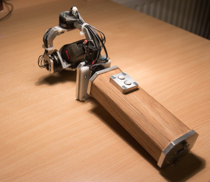
What can you do when you have a nice CNC machine, but build beautiful things like this 3-axis gimbal? We covered some of [Gal]’s work before, and he does not subscribe to the idea that hacks should look like hacks. If you’re going to spend hours and hours on something, why not make it better looking than anything you could buy off-the-shelf.
The camera is held stationary with three hollow shaft gimbal motors with low cogging. We weren’t aware of hollow shaft motors, but can think of lots of sensor mounts where such a motor could be used to make very compact and smooth sensor mounts instead of the usual hobby servo configuration. The brains are an off-the-shelf gimbal controller. The gimbal has a DB9 port at the back which handles charging of the internal LiPo batteries as well as giving him a place to input R/C signals for manual control.
The case is made from CNC’d wood and aluminum. There are lots of nice touches. For example, he added two buttons so he could fine tune the pitch of the gimbal. Each button is individually engraved with an up/down arrow.
[Gal] reverse engineered the connector on Garmin action camera he’s using so he can keep it powered, stream video, or add an external mic. Next he built a custom 5.8Ghz video transmitter based on a Boscam module. The transmitter connects to the DB9 charging port on the gimbal.
It’s very cool when someone builds something for themselves that’s far beyond anything they could buy. A few videos of it in operation after the break.


“the most CNC machine ever made”
What does that mean, exactly?
It is the truest of cnc machines. The proto-cnc, if you will, or Ur-cnc if that’s your bag. It is the cnc machine all other cnc machines are attempting to imitate. It is the cnc machine that spans time and space, and transcends causality. Never before and never again will there be a cnc machine as cnc machine as this one.
You guys are making me regret fixing the article so soon. Haha. I’m going to use this as the specification header when I build myself a CNC later this year.
“the most computerized numerical control machine ever made” precisely.
Haha, there was an error somewhere a long the chain. We were trying to bring attention to a cool Solvenian Community CNC project by using the same phrase [Gal] used to describe it in this comment thread: http://hackaday.com/2016/02/19/turn-your-10-dollar-mouse-into-a-fancy-10-dollar-mouse-with-cnc/#comment-2926584 .
It didn’t work out, but hopefully this edit makes more sense:) Thanks for pointing it out!
.Why is it common to use direct drive BLDC motors for camera gimbals like this? It seems like using medium or low ratio geared servo motors or steppers would make much more sense: The gimbal would be lighter because the motors are much smaller and the gears would be non-metal, any torque issues go away, cogging problems are dramatically reduced with geared motors, and speed is not really an issue in an application like a camera gimbal. In-fact if steppers are used, it may be possible to eliminate costly position feedback all together because the flights are of limited duration.
By the way, smooth direct drive BLDC motors in an application like a camera gimbal not only require careful (read expensive) design to reduce cogging, you have to pay special attention to the actuator you choose. The actuator should have learning-adaptive pre-distortion anti-cogging (read again, expensive). This is yet another reason to question why direct drive BLDC motors were chosen in the first place?
By the way, the link on the Author’s page to the motors he used is not working (for me right now anyway). But the motors aren’t hard to find; just do a Web search for “BLDC Gimbal Motor” and add “Hollow Shaft” to the search if that’s what’s particularly interesting to you.
Noise. If you are shooting video and using a mic on board you will hear every whine and buzz coming from the gearbox. It also makes it significantly smaller to use direct drive motors.
Steppers are the worst, you will have a considerably slower feedback time. And they are just noisy, mechanically and acoustically. And they are not using position feedback with the brushless motors, the feedback is from the accelerometers/gyros. You cant beat the weight and size of a direct drive motor, especially ones like used here with lots of poles to give you lots of low speed torque.
I have taken apart gimbals that came out of scaneagle drones and they do use a zero backlash planetary stepper for general pointing but for the stabilization and tracking they use voice coil motors.
And there is nothing to design with the motor drivers, you just buy one off the shelf, make mounts for the motors, hook up gyros, and the spend a lot of time fine tuning it.
Compared to brushed motors, brushless ones have less noise, longer life, increased efficiency and higher power-to-weight ratios. They also allow for outrunner designs where the bell housing rotates rather than a shaft – so there can be through hole designs like these. With special consideration when designing the coils they can also have low-RPM and high torque, kind of like adjusting the gear ratio without the gears, but you don’t have to do the design work, just search for “brushless gimbal motors” many companies provide them already.
And since there are no gears there are less moving parts, less inertia, and almost no slop – the tendency to vibrate is fought directly by the magnets.
Problems with complex controller design and cost are not really an issue thanks to the great AlexMos/Basecam controller. AlexMos has already done the hard work, no one needs to repeat it.
Another thing I like about brushless motors and the rotating bell housing is that not having a shaft makes it easier to mount things to them, you don’t need shaft couplers or custom lathe work, just bolt directly to them. It makes them much easier to use for DIY hobby stuff.
they are also inherently a waterproof design and can even be run under water with no issue, as long as the cables leading to it have been properly waterproofed of course.
Backlash in the gear train is a pain to deal with in the control system. If you sense (encoder) at the motor, you get position ambiguity on the far end of the gear train. If you sense at the end of the gear train, the servo hunts back and forth in the gear backlash. Direct drive avoids this completely.
Thanks for the thoughtful replies…
Noise: Yup, I didn’t even think of that at first. I was thinking “Drones” where noise isn’t an issue.
Backlash: I’m not 100% buying into that one yet. But it’s worth a thinking about.
On the backlash, If you put the position encoder on the output of the gear train, when when the servo is holding position, there is usually a small error, so you turn the integral gain up to make it go away. What happens is the backlash adds enough delay between the time that the motor actually starts moving to reduce the error and the system getting the news that it is in motion again and the servo overshoots the correction, maybe by a small amount, but still, a non zero error. Then this process then repeats in the other direction. Also, with the backlash, the motor delay allows the motor to get moving faster than it would have with no backlash and when the backlash closes up, there is too much energy already in the system, aggravating the overshoot.
Putting the encoder on the motor eliminates these issues, but the pointing accuracy is reduced by the amount of backlash in the gear train.
So how much did the whole thing together end up costing?
I don’t know if you’ve ever tried any of the EVO Gimbals, but I suggest you check them out at https://evogimbals.com. I bought one for my DSLR camera and it works great. Let me know your thoughts on it.