We have lost something in PCB design over the last few decades. If you open up a piece of electronics from the 1960s you’ll see why. A PCB from that era is a thing of beauty, an organic mass of curving traces, an expression of the engineer’s art hand-crafted in black crêpe paper tape on transparent acetate. Now by comparison a PCB is a functional drawing of precise angles and parallel lines created in a CAD package, and though those of us who made PCBs in both eras welcome the ease of software design wholeheartedly we have to admit; PCBs just ain’t pretty any more.
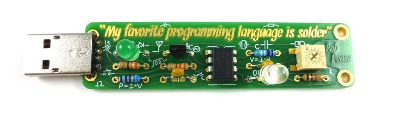
It doesn’t have to be that way though. Notable among the rebels are Boldport, whose latest board, a tribute to the late linear IC design legend [Bob Pease], slipped out this month. They use their own PCBmodE design software to create beautiful boards as works of art with the flowing lines you’d expect from a PCB created the old-fashioned way.
The board itself is an update to an earlier Boldport design, and features Pease’s LM331 voltage to frequency converter IC converting light intensity to frequency and flashing an LED. It’s one of the application circuits from the datasheet with a little extra to drive the LED. Best of all the kit is a piece of open-source hardware, so you can find all its resources on GitHub.
We are fans of Boldport’s work here at Hackaday, and it should come as no surprise that we have featured them before. From one of their other kits through several different pieces of PCB wall art, to their work making an appearance in Marie Claire magazine they have graced these pages several times, and we hope this latest board will be one of many more.


Man… now that is a quote worth having attibuted to you…
“They took the credit for your second symphony
Rewritten by machine on new technology
And now I understand the problems you can see
Oh a oh
I met your children
Oh a oh
What did you tell them?”
“Video killed the radio star”
Something has to change,
undeniable dilemma.
Boredom’s not a burden,
anyone should bear.
Constant over-stimulation numbs me
and I wouldn’t have it any other way.
It’s not enough. I need more.
Nothing seems to satisfy.
I don’t want it.
I just need it.
To breathe, to feel,
to know I’m alive.
… … …
*** Something kinda sad about,
*** the way that things have come to be.
*** Desensitized to everything.
*** What became of subtlety?
*** How can this mean anything to me
*** if I really don’t feel anything at all?
*** I’ll keep digging till I feel something.
Elbow deep inside the borderline.
Show me that you love me
and that we belong together.
Shoulder deep within the borderline.
Relax, turn around and take my hand.
It’s Friday, Friday, gotta get down on Fri daaaay…
/win
Olivetti Programma 101 board. 1965: https://flic.kr/p/qrmGz1
This is amazing-looking. I wasn’t aware of that one. Thanks!
Wow, that’s a board of beauty! Thanks for posting it!
When I was a kid over 3 decades ago, I snatched this exact board for cheap from a local surplus store, brought it home, desoldered all transistors and diodes to repurpose them in other circuits and threw the remains away.
Now I feel so guilty…
Don’t worry. We’ve all committed similar crimes against junk, I’m sure.
Still, could be worse. I’ve gotten hold of many such boards with a friend when we were 8-9 year olds. We blew up the germanium diodes as that gave a nice bright flash :) We also put some amps on thin traces which also went out with a pop ;)
Talking about feeling guilty now :) I maybe still have a handful of working diodes from the hundreds that were on that board.
Gorgeous.
Hello everyone.
I’m Saar from Boldport. In the interest of self promotion, you can get this kit through the Boldport Club ;)
https://boldport.cratejoy.com
Let me know what you think!
If only they could mimic the smell of old electronics to go along…
Need phenolic PCB material instead of the newfangled FR4 to get the authentic smell. And also proper rosin core solder….
And dust. Especially when heated by vacuum tubes.
Yup, the right old rosin core solder alone will produce that smell. Last year I got a few very old kits (~40 yrs) from a shop for cheap. The original blister was damaged and they swapped it for an anonymous plastic bag, but all contents were there including a short piece of very thick solder wire, like 1.5mm. As soon as I tried that solder, that smell brought me back by at least 30 years!
I have and regularly use 20+ years old 60/40 solder wire (also avoiding that lead free junk) but that little piece smelled a lot older and stronger.
Here: http://www.taydaelectronics.com/copper-clad-board-pcb-single-side-6×6.html
I can’t take it anymore! (goes crack open the 60 year old tube radio for a quick fix)
i bet those hand drawn curvy traces are a lot better at dealing with mechanical stress.
You don’t need special CAD software to have curvy traces. DIPTrace does them, Altium does them (I think) and probably any other software I don’t use does them or can be made to do them via plugin or script. I did curves in DIPTrace in two of my projects just because I like them. I even used copper pours to get those sexy shapes thy did with tape whenever two or more pads were next to each other…
You can do some pretty neat stuff in DipTrace for sure. One thing I like is the ability to import vector images from Inkscape into the design (e.g. the silkscreen). Also, OSHPark can handle DipTrace designs easily.
All the components are still orthogonal though, not like the old days. :)
In a similar vein, pre-cad pencil drawings could also be works of art. I still run across them at work once in a while, and can almost smell the ammonia from the blueline machine.
The first thing I noticed was all the bad solder joints…
Looks like one pin on the transistor got soldered properly. ;)
I’m not sure I agree with you, but maybe that’s because I’ve seen this pic of the other side of the board. https://photos.google.com/share/AF1QipN8epwk55scLdhR03kjZIWljHV5gzT2qagw81gKA4RKwvEYmjTlZVOVlRCoFwUsjg/photo/AF1QipOCFxyx70jTBoOVowfemsmb95ZhF3MlZXQyfDKk?key=T2t6b0tDbDF1elQ1OUFzeEItcF9ZN0gtN3ZHcTJR
If I turned in a double sided board soldered like that back in my high school electronics class I would fail. ;)
Our teacher was retired Navy, and he expected all soldering to be Mil spec.
The solder should have a nice fillet on both sides, no exposed copper. i.e. solder after clipping the thru hole leads to the correct tail length for the board thickness.
Anyway, that was the first thing I noticed,
Wolf
The problem is that the signal integrity of a curvy line is not as good as a properly mitered corners. Extra copper that makes the curve have higher capacitance than desired. Not to mention the difficulty in length matching and line spacing. At the clock speeds used in the 70s this would work, and work well, but in the high speed digital world (and high frequency radio world) such things can’t be effective used.
http://www.microwaves101.com/encyclopedias/mitered-bends
Call it art if you want, but to me that board is just UGLY. Rather than looking organic, it just looks sloppy. Even in the old days, they placed components parallel to the major axes of the PCB and lined up rows of similar-sized parts, and of course with crepe tape you would NOT get the variable-width lines that this board has. Also, component numbers and other text were done using press-on letters or with a technical pen, with a great deal more pride than is in evidence here.
Congratulations, you have invented the PCB equivalent of Comic Sans. Not elegant. Bob Pease is spinning.
Comic Sans? That is harsh.
PCB equivalent of Fiat Multipla sounds better?
Reminds me of the free-angle designs that the TopoR autorouter will produce if you let it:
http://www.mikrocontroller.net/attachment/81538/topor.jpg
I, too, find these aesthetically pleasing, and I like that traces don’t necessarily run parallel unless you tell them to.
By far, the most amazing part of this is that they have a fancy typeface for the text on their board. I wonder how many conversions between TTF, SVG, DXF, DWG, BMP, XLS, coordinate lists, various forms of scripts, and however many other formats that took to make work.