Almost everyone who is involved with 3D printing thinks to themselves at some point, “this could all be done using a closed-loop system and DC motors”. Or at least everyone we know. There’s even one commercial printer out there that uses servo control, but because of this it’s not compatible with the rest of the (stepper-motor driven) DIY ecosystem.
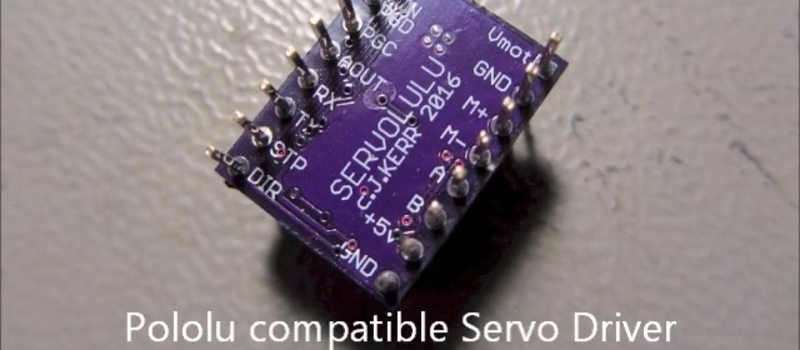
[LoboCNC] wanted to change this, and he’s in a unique position to do so, having previously built up a business selling PIC-based servo controllers. His “servololu” is essentially a microcontroller and DC motor driver, with an input for a quadrature encoder for feedback. The micro takes standard step/direction input like you would use to drive a stepper motor, and then servos the attached DC motor to the right position. It even signals when it has an error.
The unfortunate side effect of [LoboCNC]’s old day job means that he can’t release the code that’s running his demo, but he says he’s working on a version of the firmware to open-source. Have a look at a demo video (below) of his modified servo printer that’s being driven by a standard stepper motor controller. It is certainly accurate!
If you want to get up to speed on all of this stepper vs. servo stuff, this video tutorial by [Homofaciens] is very much worth your while. In fact, it’s implementing a (non-PID, primitive) version of exactly what [LoboCNC] is aiming for. Which is not to take away from [LoboCNC]’s idea: shoehorning servo control into the existing form-factor of a stepper motor driver is a great idea, because it allows quick experimentation with a new motor drive mode. We can’t wait to see the software.
Anyone else taken a similar approach to closed-loop control on their 3D printers? We gave up ages ago, deciding that steppers were “good enough” when compared to the hassle of a complete redesign, so we’d love it if the “servololu” proved us wrong.
Thanks [Matt] for the tip!


Nice idea. A long time ago I built a hybrid stepper/servo system to modify a Unimat lathe for CNC. I was using aTRS100 as a controller so that shows how long ago! I actually used both a servo motor and a stepper motor connected together with quadrature feedback for position. The servo motor was used alone for fast traversing and the stepper was used alone for fine movement. The quadrature encoder ensured precision. I was planning to allow both to work together to provide additional torque for fine positioning as my steppers were not very powerful but that proved too difficult with the available technology. It would be interesting to try the approach today.
You can buy hybrid stepper controllers off the shelf, even with NEMA compatible motors that have encoders already installed on them…
They aren’t even all that expensive, unlike servo drivers.
From 2014, servos driving a MakerGear M2 using stock electronics. Check out the two videos in the post: http://forum.makergear.com/viewtopic.php?f=10&t=1316
No details on what servos he used though.
This isn’t exactly the same, but misan released a nice bit of code for an arduino micro and an h-bridge that runs a dc motor closed-loop with a rotary encoder. It has both a step-direction interface and a serial interface. I’ve built one and it seems to work very well with a gearhead motor. Getting it tuned with a low inertia servo motor is quite tricky, but he has some code for pid autotuning as well. He also stores the pid values in eeprom. I’m in the process of devolving his code a bit to make a closed-loop spindle speed/direction control that takes gcode spindle speed commands.
https://github.com/misan/dcservo is his code. It may have shown up on hackaday at some point.
Right you are! http://hackaday.com/2015/01/20/closed-loop-control-for-3d-printers/
This thingie may ve too little to get things righ. The system needs to be MIMO (two inputs, two outputs for a CNC ot a 3d primter) to properly perform anything more than movements along the axes. Am I wrong?
Yes
How so?
Biggest question is WHY? Steppers are more accurate, and its not like they are expensive, plus all the controllers are already made to work with them. Why reinvent something that isn’t broken?
there is little to prevent you from making servos from stepper motors, a servo is a motor with feedback to allow for precise control.
the commercial large scale printer i know of all use servos, mind you i am talking of actual commercial printers and not hobby machines.
then again very few of those are FDM printers and similar techniques are used on large cnc mills.
Not true, our $70,000 Stratasys uses stepper motors.
To address OP’s question, servos make sense for CNC milling machines, as occasionally a clamp might slip or your end mill might dig in and cause more machining force than you wanted. Unless you’re over-rating your steppers by more than this amount, you will lose steps. Servos are great there. Regardless of how much momentary torque the motor is fighting against, the controller will always make sure the motor catches up to where it should be (or it’ll throw an error to stop the job).
On a 3d printer however, steppers are definitely the better choice.
I am not sure they are more accurate. It would depend on the resolution of the encoder vs the number of steps per revolution of the stepper. In most cases I imagine the encoder will have finer resolution. Micro stepping isn’t great for accuracy as far as I can tell ( but does make the motor run smoother )
In a 3D printer a stepper can be mispositioned by running into something like a cold plastic lump..
Then you’re entire layer, and all subsequent layers, are off.
If its a servo then it will correct very soon and be back in position.
Servo FTW…
I was always under the impression that servo type devices with a brushed dc motor and feedback system often overshoot and then settle on the correct position because of the gearing / inertia, totally unstable action for 3d printing.
Only a servo loop that is not tuned well will overshoot to any significant degree. How much it physically overshoots will be determined by the encoder pitch.
Steppers are a ‘digital’ device, they have a discrete set of points that they can stop at, typically 200. Various tricks with electronics and software can twiddle the voltage and current to make a stepper hold positions between the 200 ‘native’ points.
Servos are analog devices. They turn with continuous motion. Older servo systems used a tachometer to report the motor speed and linear scales or rotary encoders to sense the actual machine (or robot joint) positions. The hot thing now is putting rotary encoders directly onto the motors and inferring the machine position via belt/gear/screw ratios.
The genuine hybrid type of stepper motor puts a rotary encoder onto the motor, combined with a sophisticated controller. That can achieve almost as smooth of rotation as an analog servo, combined with the holding torque of a stepper – which analog servos using standard AC or DC motors don’t have. That’s why some servo systems had brakes on the motors, for holding position during straight cuts without having to keep high power going to the motors.
Then there are variations such as brushless DC or AC motors with skewed rotors. They’re expensive but they can do the smooth ‘notchless’ running like an analog servo motor AND hold position like a stepper.
You may see stepper motors with the controller attached directly to the motor, called “hybrid”. If it doesn’t also have an encoder and/or employ some other fancy tricks to make it work in a non-stepper fashion – it’s merely a stepper motor with a controller mounted to it.
Look up Moog Animatics Smart Motors. Fancy servomotors with built in, programmable, networkable controllers. They can be mounted in place of common stepper or servo motors then daisy chained together for much simpler wiring. Animatics has been making those since the mid 1990’s. If you have an old Animatics product not on their website, email and ask nicely for info. They do have a bunch of old backups, and old employees from before Moog bought Animatics.
I finally obtained technical and programming info and software for the Animatics 5000 series servo controller in my Light Machines PLM2000 milling machine. https://www.dropbox.com/s/8o87wzopl4yyjae/CD5XX6.zip?dl=0
If I want to work out how to do it, I could set it up to load a G-Code file then run headless. Light Machines and Intelitek only used the DNC mode. Hopefully now with this information, the Linux CNC gurus will be able to add support for these mills so something modern can be used to run them instead of the crusty old DOS software.
I work for intelitek, and recently obtained a plm2000 of my own. I’m working on making. A Java interface for the machine.
a servo is just a motor with feedback, no matter motor type.
Yup – something a lot of people don’t actually understand.
It’s looking like buddy’s using brushed DC motor. Which is really the only way you can get the cost low. BLDC need more circuitry and hall effect sensors, additionally adding to the cost. Bushed DC will eventually wear out… and with printing being such a long process. My guess is sooner then later.
The bottom line is stepper are so popular because unless you miss a step you know where you are, the reason for missing a step is mechanically loading the shaft too much – mech. load in a printer is consistent (unlike a CNC)
Unless you’re gaining some sort of massive speed advantage I don’t really see the point
more than skewed windings, (iron) coreless windings are important.
See Micromo/Faulhaber/Minimotor, Escap, Maxon and other brands of uberprecise (miniature) motors – traditional brushed DC and brushless as well.
Maybe because stepper motor needs constant current?
to hold position, a dc motor also require some current. though that will not be constant, but instead proportional to the load attempting to deflect it.
Steppers are not more accurate, even at their native step resolution they can be off. Then you start adding micro stepping which is terribly inaccurate, often time between mictosteps the motor will not even turn.
Commercial servo motors by yaskawa and mitsubishi have up to 24 bit absolute encoders on them, thats 16.7 million counts per rev. And they are very accurate.
These will work on RAMPS, if someone modifies the Arduino code?
No need to modify code. Just replace stepper driver and motor with new one.
That’s exactly the gimmick. Plug-n-play stepper to servo replacement. I should have said that one sentence in the article. :)
Check out this guy:
https://www.youtube.com/watch?v=rqPk3l3Lr-c
Not only is he brilliant, he even released the code as open source (https://github.com/misan/dcservo/) and continues to experiment with different sorts of feedback loop devices (i2c magnetic sensor, etc.).
Based on his code, I am re-building failed ToyRep printer for closed loop – the X axis is already working (extremely quiet and fast, too, at least comparing to the original ToyRep…). The Y axis follows now – have to rebuild the motor mounts and make new carriage with the encoder built in.
The best thing is the cost – I salvaged the motors, belts, encoder strips and encoders from old HP inkjet printers I got for free. All I had to invest was 2x ATtiny85 and one motor driver (currently TB6612FNG).
The target is to create a drop-in replacement for RAMPS – 2 stepper sticks will be replaced by single servo-to-stepper stick.
I am very close to release the images and videos regarding this.
Good to know someone else is working on it, too.
I built my CNC router pretty much exactly following the same pattern — salvage DC motors and encoders, some from HP inkjets also. http://www.dansworkshop.com/2016/04/large-gantry-cnc-router/ There are many advantages to this. First of all, driving large, heavy steel and cast aluminum mechanism with a 1.25HP router on it would take big steppers, and high powered electronics with fans blowing across them. I drive the entire machine from a single 230-watt ATX ps. Motors are DC brushed motors and 13-amp mosfet h-bridge driver boards that don’t even require a heatsink. The drivers are Atmega-328P’s (one for each axis) with special firmware that was inspired by misan’s build: https://github.com/dynamodan/ClosedLoopDC . They are compatible with the step and dir signals that come from an Arduino clone running GRBL, exactly the same as you would connect to a stepper driver.
Wow, any chance you made a video out of this build? I am sure Miguel Sanchez would love to see someone re-using his code. And I would love to see it in action.
Could get interesting if you can combine it with one of the high resolution magnetic rotary position sensor, like the ones from AMS.com. Even better tho would be to use direct feedback from a linear sensor, so you could compensate for all the errors introduced in the rotary drive system (backlash,..). AMS does have magnetic linear sensors too, guessing from the volume prices on theyr website you would have to pay around 20$ for the sensor IC and a 300mm magnetic multipole strip. From what i could pull out with a quick datasheet scan, these linear sensors work at up to 650mm/s and offer an absolute accuracy of around +-10um, that would be really impressive and well enough for any 3D printer and most micro cnc machines.
Have thought that before, why read the feedback position from the motor shaft when it could be the bed position? If not magnetic linear sensors what about cheap digital calipers?
Recall mentioned here that backlash in the drive train and bed position feedback = motor hunting back and forth trying to get bed in correct place. Could be tuned out perhaps.
SX2 mill with standard leadscrews driven by scrap 12V drills is the experiment I am pursuing. Bed position to be provided by calipers attached, though finding a dirt cheap 200mm caliper locally is proving difficult.
It’s really hard to tune a system where you have the feedback on the load. If there’s any slop in between the shaft of the motor it’s borderline impossible. If there is zero or next to zero slot it’s possible but then at that point why wouldn’t you go off the motor shaft.
We’re still trying to switch over from a LEDs-based tracking system to one using Jay Dosher’s code (https://github.com/polyideas/Raspberry-Pi-Solar-Tracker/tree/master/Software%20(File%20System%20Root)/usr/lib/cgi-bin). We have finally got the code ported to Python3.x although we know almost nothing about programming – thanks to all who have helped so far! However we have come to find out that we will be needing another type of motor because the one we have been using, a DAYTON – DC Gearmotor 12VDC Nameplate RPM 17 Max. Torque 30.0 in.-lb. It also lists it as being only 1.4 full load Amps, appears to not fill the bill due to it not being a stepper motor. Can any of you guys/gals recommend a replacement stepper motor for this thing? We went ahead a purchased a Nema 23, 24 kg. cm., 4 wire, but it’s much heavier than the Dayton and it’s 2 Amps.
Does anyone have any ideas on this? i’m running this with a Raspi B at this point. They have also mentioned that we’re probably not going to be able to use the L298 H-Bridge with this setup. Uf, this is much more complicated than i thought it was going to be.
People say if you “get into it” you actually learn programming. i must disagree since what i really learn is which forums can help out when the program runs and finally reports an error. i think one of the most helpful forums is Stackoverload if one can figure out how to properly craft the question – lol.
Have a great day! :)
Steppers actually work really well for most 3D printers, especially when coupled to a belt drive which adds a little compliance. For other types of systems where the load varies considerably, steppers can be difficult to use and you end up having to oversize your motors considerably. Also, for systems with very rigid drive trains (ie, leadscrews), vibrations can cause the motor to lose steps under relatively light loads. Servo control systems are generally more forgiving, quieter and smoother than steppers. The real advantage for 3D printers, though, is the potential to monitor the position errors through the serial port. This can tell you if you are trying to drive the motors too fast or if it is taking too much force to extrude the filament. Even without a serial port monitor, the current Servolulu implementation has a fault output you can use to terminate a print if the servo craps out for some reason. Hopefully I’ll get some open-source code put together soon.
I’ve opened up a ton of printers and most of them use a DC motor with an encoder on the back.
The kicker though, is a lovely thin magnetised ribbon and sensor on the printhead that report accurate position. This results in 4800DPI resolution. (50micron if my math is right) This is basically a linear encoder.
Get that into a 3D printer and things like layer shift/auto pause&restart will be a problem of the past.
A capacitive strip similar to the ones used in digital callipers – would work great as well.
The thin ribbons are not magnetized, they’re just plastic strips with fine lines printed on them, read by an optical sensor.
Inkjet printers drive the DC motor “past” the desired point every time. While it can accurately squirt at very high resolution on the fly, it would be quite a different task to STOP accurately at a given position.