People seem to be rather into the Unitree Go2 quadruped robot, if only for the low price tag. But perhaps more interesting are the motors that propel it — they appear to be similar to the Go1’s GO-M8010-6 motors that Unitree also sells, with [Thomas Flayols] currently working on reverse-engineering its proprietary driver using the publicly available documentation for that motor and some reverse-engineering.
These motors are an assembly that includes a reducer, magnetic encoder, 3-phase inverter, current sensing, an RS-485 bus and a Cortex-M0-based CMS32M57xx MCU, all in a very capable package intended for robotics applications where a compact actuator is needed.
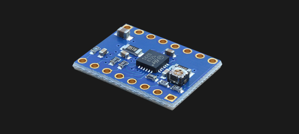
The first step of reverse-engineering involved the physical PCB, made all the more difficult as Unitree was so kind as to remove all markings on the ICs. Fortunately using an X-ray machine and some sleuthing it was possible to deduce the MCU and other components. Following this SWD/OpenOCD access to the MCU could be established and the firmware key extracted from the bootloader SRAM.
Although the firmware was encrypted, a locally recovered key was found to decrypt it. This allowed for an initial custom firmware to be developed, which [Thomas] hopes to develop into a fully featured open source firmware. Doing so would obviously open these motors to a larger audience outside of Unitree’s ecosystem, as they are pretty good value for what they offer mechanically.
It might give the associated Go2 robot a new life too considering the serious malware accusations and security issues pertaining to its firmware.