If you’ve ever needed an example of colossal failure of government actors, you need only to look at Flint, Michigan’s water crisis. After the city of Flint changed water supplies from Detroit to the Flint river, city officials failed to add the correct corrosion inhibitors. This meant that lead dissolved into the water, thousands of children were exposed to lead in drinking water, a government coverup ensued, [Erin Brockovich] showed up, the foreman of the Flint water plant was found dead, and the City Hall office containing the water records was broken into.
Perhaps inspired by Flint, [Matthew] is working on an Open Source Lead Tester for his entry into the 2016 Hackaday Prize.
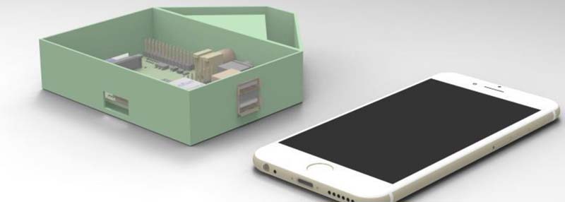
[Matthew]’s lead tester doesn’t test the water directly. Instead, it uses a photodiode and RGB LED to look at the color of a lead test strip. These results are recorded, and with a bit of a software backend, an entire city can be mapped for lead contamination in a few days with just a few of these devices.
One problem [Matthew] has run into is the fact the Pi does not have analog to digital conversion, making reading a photodiode a little harder than just plugging a single part into a pin header and watching an analog value rise and fall. That really shouldn’t be a problem – ADCs are cheap, especially if you only need a single channel of analog input with low resolution. [Matthew] is also looking into using the Pi webcam for measuring the lead test strip. There are a lot of decisions to make, but any functional device that comes out of this project will be very useful in normal, functioning governments. And hopefully in Flint, Michigan too.


Awesome project, but do you really need a Raspberry Pi? Even a Raspberry Pi Zero seems like overkill.
A ESP8266 has an A/D port and if you really need a camera, you can get a JPEG camera module with a serial output.
But seriously, awesome project, good luck with it.
Not to cast aspersions on a well-meaning project, but…
Don’t test strips have a color comparison chart printed on the package?
I don’t see how this project is better than just comparing the strip against the chart and typing the numerical value into your phone.
I can see this as a project that uses known light sources and amounts to record accurate readings instead of the varying readings you get from the human eye. Add Geotagging to it and you’ve got a plot map that can identify significant areas of corrosion and allow for targeted repairs that fix the issue faster than a shotgun approach.
Same with urine dips, they are usually machine read now anyway, it waits the corrent time, doesn’t have confirmation bias and is objective.
I used to work on designing photometers for this very task, and this does look a little overcomplicated. A good demonstration of the principle though. ‘Real’ photometers use much less CPU (particularly single test ones like this), low end PICs used to feature heavily in our developments.
Also, analogue inputs and outputs are not required… you’ll have to work that one out for yourself though :-)
Hi Rolinger,
color me intrigued! I was thinking about building a simple photometer too for a process that needs to be controlled a little tighter at work. For the circuit, the Idea I came up with was to use a photodiode, one of the TI special logarithmic amplifiers e.g. http://www.ti.com/product/log2112 and then an ADC.
Are you charging a capacitor with the photocurrent until its voltage is above a threshold, then trigger a comparator into a digital input and determine the time? I don’t see the circuit in front of me yet :D
That old trick of using an R-C circuit as a rudimentary A/D converter? ;)
If you have a diode with an exposed junction – virtually any diode in a clear casing – all you need to do is connect it between two IO pins. There’s no other components necessary. No RC network, nothing.
The diode has some junction capacitance which is charged up by the light striking on the diode. You bias the diode in the blocking direction to discharge the capacitance, then flip the polarity around and time how long it takes for it to reach logic high, holding one IO pin as the ground and the other floating.
It works with an ordinary clear LED just fine. The same diode with a current limiting resistor added can also shine light so you can make a night light which uses the LED as both the sensor and the light source.
That old trick of using an R-C circuit as a rudimentary A/D converter? ;)
What a does a lead test strip cost?
About $5 to $10 each, if google shopping is to be believed.
Not to be confused with lead test *swabs*, which are for testing lead paint and are available at WalMart.
Also, there’s the “dip strip” device which is a commercial version of this project, available for $300:
http://www.omega.com/googlebase/product.html?pn=HHWT-14
(Not that this is a problem, especially if he can make a cheaper version.)
technology over kill? I admit I could be missing something. I assume like most test strips lead test strips are consumables, depleted once the water hits them, not useful for continuous monitoring. Get up in the morning run the tap a bit, use the test strip, use your phone to post a photo the FB. Brockovich shows up someone is going to die. That’s an uncomfortable coincidence, especially for the deceased. Clearly I hadn’t followed the story close enough to read all minutia.
So someone who wants to check the lead level in water have to: 3d printer the case, build the electronics, program the pi , connect it to the internet to share the result, calibrate the sensor, buy the lead test strip, test the water with the strip, insert the strip in the device. Instead of just: test the water with the strip and share the result on internet. Great automation! Will save time and money!
Better write a phone app which reads the strip from the phone camera in my opinion…
Or use a proper sensor for lead concentration, but currently it uses fluorescence from a DNA enzyme reaction with UV light, cuvette and spectrometer
I fully agree, using a reference color chart next to the test strip and just take a picture with a phone, let the app analyze the picture and log GPS location, IMEI and lead value, and/or directly transmit all the data to a cloud storage for statistics and what not over the mobile network. Picture taken by the camera stays with the result as a weak “proof of measurement”.
Everyone who has a somewhat decent smartphone and can get the app, buy/get a test strip can help gather data. And if someone spots irregularities in entered data, you could use the IMEI (or some other ID string in the data) to filter out all the results sent from that fraudster-phone…
Can someone please teach Brian Benchoff the concept of the basic tenses, i.e. present and future.
The project doesn’t “use a photodiode”, it WILL use a photodiode – IF it is built. And only testing will show whether or not it does anything useful.
The project doesn’t make any mention of testing for lead contamination. Where has Benchoff got that idea? Has he plucked it out of thin air, or what? (If out of thin air, why not restrict it to lead, why not also include DNA paternity tests etc :) )
“The project doesn’t make any mention of testing for lead contamination.” — It’s mentioned in the project’s very own title? See https://hackaday.io/project/10438-ospb-an-open-source-lead-tester — the title rather clearly reads “OSPb – An Open Source Lead Tester”
Doh! My bad. Should have had a cup of coffee first.
Why did I miss that? Because my eyes automatically skips over header images since they are always (except in this case!) content-free fluff or an advert for something that I don’t want. 23 years reading the web has trained me that way.
We all have our bad days, and Internet makes it *way* too easy to rage about things before all the details have actually sunk in — I would know, I’ve been there myself quite a few times! ;)
Just make sure the water you make your coffee from is unleaded!
It isn’t unleaded! I had it tested ~25 years ago and it was just (2%) under the then limit. ISTR that the limit is now 20% of the previous limit. Hence my passing interest in *accurate* test measurements.
The solution, pun intended, is to run water for 60s before drawing any for cooking or eating. That’s more than sufficient to empty the pipes between the tap and the supply in the road. No, water isn’t metered, it is a flat rate :)
If it still needs the test strips, then what is the point of the Pi? Plus the lack of ADC means he’s picked completely the wrong tech solution anyway. An impressive 200% fail.
Once he’s used the camera to detect the colour, why not display it on a screen so the user can compare it against the comparison chart. Or he could add an Arduino to do the ADC and send it to the Pi using an ESP8266.
Apparently all it does is the result’s colour matching… hardly of any help, even with all the “but on the web”. At the very least it could have integrated a GPS to upload test result directly onto a map – then again, any smartphone could do the same with a few lines of code and a 3d-printed “back case” to envelop the camera and the LED light on its back…
ADC was a massive pain with the Pi when I tried using it. A couple channels of ADC input that the Pi then used to control some PWM output was annoying, all the stuff had Python libraries, but half was for 3.x and the other for 2.x, so a bunch of the libraries for simple things like smbus to the LCD had to be rewritten and recompiled for 3.x.
Something with built in analog, or like another commenter suggested, using an app would be by far the better solution.
I think even the picaxe has analog built in, those are pretty decent and affordable and the picbasic isn’t half bad, I’ve done a datalogger with them before.
It just occurred to me, some of the people using the test strips may be colo[u]r blind.
May I suggest a design simplification?
A couple of LEDs (red, green, blue — if you really need tri-colour identification, but you may only need one wavelength/colour) and a photodiode (BPW31, whatever floats your boat), and a PIC or an STM32 to do the grunt work?
Calibrate the PD with a known “black” and “white” reference (i.e. what’s called a ‘sensitometer’ in photography) and you’re good to go.
Simpler than that: put the test strip next to a card with color calibration marks, use a smartphone app to take a picture with the LED flash on, do some OpenCV magic to find and quantify the sample and calibration mark regions, done. It’s a safe assumption that an image sensor has a uniform response across all its pixels.
At first, I thought this was going to be a lead tester, not a lead tester. But now I know it’s a lead tester.
I see where you are leading us!
I read the title and thought, what are they testing wire leads for? I use an ohm meter.
Would this have worked for Flint’s water issues? I mean that was like pre-2000k.
What are you talking about? Flint’s water issue is ongoing!
Overkill with the Pi. This can be done with an Arduino and an off-the-shelf RGB sensor from Sparkfun or Adafruit for < $10. Calibrate against black and white, normalize the color channel readings, maybe use a color space conversion to something like XYZ or cieLAB (which would make it easier to discriminate color than fiddling around with RGB values). The sketch would contain the mathematical color chart for comparison. Spit the data out over serial (connect to phone with USB-OTG) or Bluetooth and use your smartphone to post to a web service. Do not even attempt to use a smartphone camera for this. Lighting conditions alone will screw you in a very bad way.
Does anyone understand how the test strips are manufactured ? Could an electrolysis method make them reusable ?
I also see an automation prospect.
A test strip gets dipped, read by a 3 color sensor, and texted/emailed/logged all on a daily/regular basis. Once in a while a new magazine of test strips will need to be loaded, and the used ones discarded.
I don’t get it. If you’re obsessed with removing the human element (e.g., a human simply comparing the test strip color and sending the result in), then write a simple smart phone app that uses the phone camera to compare the test strip color and send the results in. No extra hardware needed.
Light-to-frequency-converters are highly accurate, cheap, and don’t need an ADC. They can be read out by the Pi’s GPIO.
http://www.ti.com/lit/ds/symlink/tsl235.pdf