No circuit is so trivial that it’s not worth thinking hard about. [Charles Wilkinson] wanted to drive a solenoid air valve that will stay open for long periods of time. This means reducing the holding current to prevent wasting so much power. He stumbled on this article that covers one approach in a ridiculous amount of depth.
[Charles] made two videos about it, one where he debugs the circuit and learns things live on camera, and another where he sums it all up. We’ll be walking you through the long one, but feel free to skip around.
Solenoids are harder to open initially than they are to keep open. So [Charles] hooked his solenoid up to a variable power supply and tested the activation and release voltages — because nothing beats empirical data. He ramps the voltage up slowly (around minute 6-7) and it just trips at 3.5 V. Testing when the solenoid closes again, he bottoms out his variable power supply at 1.25 V. Anyway, you get the point: higher opening voltage, lower holding voltage.
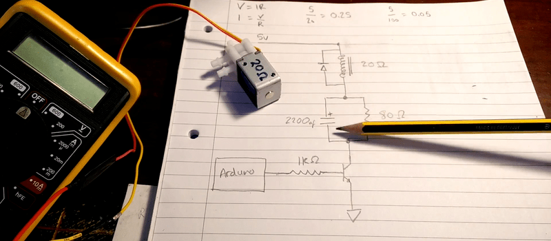
And that’s the point of Bob Pease’s circuit in the linked article. The capacitor passes current initially, but then charges up over time so that less voltage is dropped over the solenoid, reducing the holding voltage. The trick is then to pick the resistor and capacitor to just match the characteristics of your solenoid.
In the video, [Charles] builds the circuit, around minute 30, and discovers that it doesn’t work. Instead of editing that out, he troubleshoots live. (Brave!) He fails, and goes offline. The eventual problem? He was powering the circuit off of USB, while charging his phone at the same time. He just didn’t have enough power in his power supply. And then, after ten more minutes of debugging intermittents, he adds a buffering capacitor to his power rails and the problems go away.
There are two things to take away from all this. The first is a simple but elegant circuit that you can use to drive solenoids or relays or anything else with a strong initial current demand. The second is the importance of stable power and buffering.


Can’t you just PWM them after initial opening?
Sure, you could even pwm them to the point of ramping their opening/closing forces, if you so-desire.
E.G. you’ve got 88 big/power-hungry solenoids to PWM and have to make sure the PWM frequency is well-above the hearing-range. Oh, also, make sure you’ve got fast-switching flyback-diodes, and transistor-switching times are really important here!
This is a cool technique, to learn about… Other techniques I’ve seen are usually more active, using two transistors and two voltage-supplies.
Normally it is just done with frequencies in the range of 50 to 200Hz. Does not need super fast diodes or switching transistors. You get a little hum, but that is accepted.
Pro Tip:
This is exactly how you reduce relay coil power consumption. This is also an article in EDN.
You could actually run a PRBS in a timer/background and let the output modify the PWM duration (keep duty cycle constant), Bouncing between two PWM frequencies at “random” makes the squeaky noise turn into a nice low level noise-like sound. It is possible to get away with 10kHz or lower (but avoid resonance frequencies of the relais/solenoids). “spread spectrum clocking” in audio range ;)
PRBS in a typical micro-controller counter/timer peripheral requires too much CPU overhead. However, PRBS solenoid drive can be done fairly cheaply in a jelly-bean CPLD. I’m surprised more micro-controller counter/timers these days don’t have in-built PRBS register taps and XORs. The additional cost and footprint size to add the functionality seems trivial.
Or use NO valves?
NO need to shout! B^)
(it took me a moment to understand that you mean “Normally Open”, but you only reverse the problem to hold the valve closed, perhaps a latching type of actuator?)
“[Charles Wilkinson] wanted to drive a solenoid air valve that will stay open for long periods of time.”
We don’t know what “long periods of time” are here exactly, nor do we know the duty cycle requirements.
If it’s, say, a 95%, open, 5% closed duty cycle, why start with a NC valve and need to engage in extra effort to slowly open it with limited input current unless other design constraints are relevant (power off needs to be closed, etc)?
Perhaps he needs for failsafe conditions? If the power goes out and he wants the valve to be closed in failure condition.
I agree Lightningmar. I designed a solenoid lock control circuit for hospitals that was NO, and I had to power it closed at all times. Its failsafe was to open on power loss to prevent people from getting locked in, in the case of fire.
I used PWM at full duty to close the solenoid and throttled back to hold. On thing I added was an occasional full duty pulse, for one second to ensure the solenoid was closed.
That is quite a sneaky approach! Although, ‘fix it in software’ doesn’t feel as good somehow…
It’s not “fix it in SW” it’s just “do it in SW”. The advantage is that the PWM solution does away with the power dissipation in the resistor. If you really want, you could design a solution with a dual HW timer (NE556 :-) ) to PWM (one timer as oscillator) the solenoid after an initial pull in phase (the other timer as monostable).
That is a very good point. Thanks for the tip :-)
And if you’re feeling even more clever, you can monitor the current through the solenoid. Since you’re PWMing it from a probably-fixed voltage source, that means you can indirectly measure its inductance.
When the solenoid pulls in, the iron core moving into the coil raises the coil’s inductance and you can detect that. A bit of clever code can auto-analyse the solenoid to find the pull-in and drop-out currents, and to detect the current position of the core.
Only works if you have a spare resistor to use as current sense (and a spare IN to with ADC). Ultimately if power consumption is one’s concern, the way to go (as some other poster mentioned) would be simply to get a latching solenoid. Does anyone know what specifically determines if the solenoid remains engaged? A specific threshold value of joules/second? What’s the charge/discharge pattern anyways of a solenoid (e.g. is there a specific range at which you get ‘peak efficiency’ like a motors power curve? I.e. minimize the Integral(t1,t2) I^2 * V component-wise where your constraint is ‘keep latched’ ?
Since the solenoid is driven with an transistor and an Arduino, I think that driving the transistor with a PWM could do it with less components.
See http://embeddedgurus.com/stack-overflow/2009/11/lowering-power-consumption-tip-3-using-relays/
And more easy tips for relay controlling : http://jumperone.com/2011/10/using-relays/
maybe going with a servo valve is a more desirable choice, only uses power when changing states, though the transition is slower.
If there is no need to switch quickly, a motorized valve is a good way to go to minimize power consumption. You can simply used a RC servo attached to a quarter turn valve. Technically it would not be a servo if there was no feedback but the feedback pot can be used to avoid the need for limit switches.
This is probably the rightest solution for the problem that the OP has, b/c he needs to turn it off at night and on during the day — very long cycles.
That is a good idea, however I would like the system to fail with the valve closed if the power fails. With a motorised valve that is kinda hard.
i suppose a battery backup or even a super cap would supply enough power to close the valve when the power goes out. but that might be taking the whole thing a little too far.
You’ll violates USB specs by adding too much capacitance.
http://www.beyondlogic.org/usbnutshell/usb2.shtml for those who can’t be bother to download and read the full spec.
> Inrush current is contributed to the amount of capacitance on your device between VBUS and ground. The spec therefore specifies that the maximum decoupling capacitance you can have on your device is 10uF.
True, but it may work: cheap HW will just have a poly fuse that will not trip with plenty of capacitance. Good HW will shutdown.
I have one of those 10 port 2.4A USB power thingies. Pull the max current in DC, no problem. Plug in something with 220uF on input…nope it shuts it down.
would a coil to dampen the inrush work?
You would probably need a lot of inductance.
Polyfuse works by limiting current, so eventually the cap would charge up. A good USB host/hub implementation uses USB power switches (electronic fuse), but are rare these day. I use those type of hubs for testing prototypes.
Power supply trips on over current is actual a safety feature. Some uses hick up as a recovery mechanism so eventually the cap gets charged. Hick up type of protection is really bad for some devices, so there are latching ones. e.g. HDD as the heads can crash when the power supply goes no/off in short durations.
I’m not sure I follow? The circuit isn’t powered by USB – I’m using an old ATX PSU converted into a bench supply.
Ah, I see the mis-understanding. The HaD article said I was powering off of USB while also charging my phone with the same USB power supply (an easy mistake to make as I didn’t fully explain how I was powering the circuit in my video).
In reality, I was powering from an ATX PSU bench supply to which I have added a USB port powered by the 5v rail. This was what I was charging my phone with and also powering my circuit. As such, the supply should have been quite capable of providing enough juice for both.
I think the problem was that the supply couldn’t respond quickly enough to the sudden nature of the change in current demand. As such, I had to add the smoothing cap.
Didn’t see the video but if his “arduro” has a microcontroller in it :) he can save more power with using pwm. This will turn the coil of the solenoid into a part of a smps and he doesn’t have to waste any power in the 80 Ohms resistor. Use a high pwm duty cycle to activate and reduce pwm to hold it open. Using a fet instead of a bipolar wil also increase efficiency.
Oops, I’m about the 10th to suggest this. An option to remove my comment would be nice…
NO! We like seeing people wallow in despair! B^)
And think of it as voting. Right now, it’s looking good for PWM, although I’d personally go with motorized on/off.
Yeah PWM does seem like the popular choice. Not sure I like the ‘fix it in software’ approach. It just doesn’t feel as elegant for some reason.
There’s a number of purpose built ICs for that as well. Probably the easiest one to find is the LM1949. You do wind up with a bit of a higher component count, but can use it with just about any supply voltage within reason and it can even adjust current as the supply voltage varies.
You do not need this, if you drive the solenoid from a microcontroller anyway. Nearly every µC has PWM timers.
Opening this valve without being inline with a pressurized circuit, gives you other values for voltage and current (it’s the current that opens en holds the selenoid) then being pressurized. Especially when the valve works for a vacuum, where opening the valve may cost a bit more power (pressure outside the moving parts and inside). Since the measured values aren’t that high, I would test both situations before choosing the other components.
There are, as says, IC’s for that purpose. These measure the current and rising or falling of it; the characteristics of the selenoid. That is the proper way to do it. Over and over again at variable pressures.
However, his solution is nice and conserves power and – most important – he learned a few things. We are only spectators of that process and can argue about it.
Good point! More testing should be done with a load on the solenoid, (a vacuum, or pressure, or for an open solenoid suspending a weight from it.
Very good point! Although the mechanical design of the particular solenoid means that pressure in the system shouldn’t impact the power required to switch the solenoid.
Hard to explain in a quick comment, but the positive pressure input presses on the side of the sliding barrel of the solenoid, not in the plane of its motion.
still adds friction if the barrel is pushed laterally
Yeah true, but the bore is tiny and the pressure is pretty low so hopefully it will be ok. At least I know to look out for it now.
Thanks :-)
An even better solution is to use a magnetic latching solenoid, which only needs power to change state Permanent magnets hold the valve open/closed after movement. Yes, they are more expensive, but ideal for low power applications.
Here is a video showing how they work: https://www.youtube.com/watch?v=eKdtLnny2dQ
If they are like latching relays, you usually do not know what state they are in when they are first powered up.
Yup, this is the answer right here. Magnetic latching relays are used in all sorts of lawn watering timer and irrigation systems. Infact, i’m about to use one on my own custom lawn watering system.
I’m not saying its not impressive, but there are other solutions that are much easier.
Any idea where to find very small valves like this?
I would like to build a DIY drip irrigation project, where each plant or community had a solar powered sensor and valve to minimize garden water use in my arid environment.
But usually, such latching solenoid requires to be powered with reversed voltage to “unlatch” so it means a H-bridge and thus more complex design (4 transistors instead of 1). A simple capacitor for energy storage plus a single mosfet driven in PWM is enough for such simple control.
I worked for a company where they did PWM and hysteresis to reduce relay on-state current consumption; nice approach when your design must be energy efficient
If you are able (NDA allowed) could you give a source/part numbers?
I just use a nice driver chip like MCP1407 for my pinball solenoids and PWM the hold open. easy peasy.
“The first is a simple but elegant circuit that you can use to drive solenoids or relays or anything else with a strong initial current demand.” I would argue that in this day and age the elegant solution is to use a much more complex IC that does this better than the bulky capacitor: http://www.ti.com/lit/ds/symlink/drv120.pdf
Unless your doing a junk box build… I have used this technique and it works very well. I think that sometimes we forget that just because there is an IC available, it doesn’t mean we have to use it… By this logic we should use an ic to drive every LED we use, because it would do it better that a simple resistor. What ever happened to good enough? The same could be said about 8 bit versus 32 bit micro controllers… (ducks to avoid being hit by the flying stm32 dev board flying across the room)
Yeah, I’m with you on this – Hard to know where to draw the line. I must admit that using PWM would be a more efficient solution but somehow it feels less satisfying. Maybe its that the perf board would look boring without all the passives :-)
Come to think of it, you can actually implement the function with discrete: use 2 transistors, one with the resistor moved to the emitter, one without. The one with the emitter resistor keeps the base resistor, the other one gets driven in the base with a C, much smaller than the original one. On startup the transistor without emitter resistor gets briefly driven turned on, until the base capacitor charges.
Or you could use 2 pins, 2 drivers.
Many ways to do it….. if you want to skip the large C.
A technique often used in diesel generators is for the fuel solenoid to have 2 coils and a switch. First coil is to start it moving and switch turns on low power holding coil. Problem is if solenoid did not fully pull it, high power coil was enough to set cabling on fire, as it was not fused due to current surge and the need for fuel solenoid to stay on even while the starter motor turning. Hence wiring fire was common, even with brand new fuel solenoid, if it failed to pull in straight away. Simple design, but prone to fires! Some sort of over temperature trip was needed as solenoid would become very hot before cabling caught fire.
I had the issue of solenoid overheating and solved it with PWM. Three years back I was building RO water purifier for my home and water inlet solenoid needs to be open for the duration of filtration. During initial tests I found the solenoid overheats after few minutes. I used a PIC controller in my design. Solution was to apply full power to operate solenoid for few seconds and then switch to PWM to hold it. It was a simple solution as it was implemented in software without the need for any modification to the designed hardware.
If you want to save power, use a latching relay. It only requires power to change its states.
https://en.wikipedia.org/wiki/Relay#Latching_relay
This is a good example of the Top Down approach mentioned in a recent HaD article. He digged in and came up with a solution but since he did not have the necessary background his solution was not very good. Then the loop is closed with the folks on the internet :) HaD comments revealed better solutions, from folks who have the background/expertise. Win! Yay!
There is an even simpler way to do this that I more typically see in industrial usages, except they pay way too much for the current limiters.
A solenoid draws the most power at startup, and then the holding current is much lower. There is a resistive device that starts high and then increases in resistance as time goes on….
Yeah, we just stick incandescent lightbulb(s) in series with the solenoid. I have a pneumatic robot arm that uses a couple parallel solder-in bulbs to control the solenoid current. Cheap, simple, effective, and no need to even think about capacitor and resistor sizing or PWM code. Stick a lightbulb in and treat the solenoid as an on/off switch and job done.
Ha! That is fabulously red-neck. No offence intended :-)
Oh, in a way it definitely is. At the same time though, it’s a cheap self-varying current limiter that can be picked up almost anywhere still.
Usually the ones sold by companies under various names and descriptions are a sealed box in a cable with one or more bulbs in it for a lot more than one can be made for. Amusing side benefit is they also give a visual indicator that power is flowing, assuming you didn’t buy the sealed off version.
This one keeps coming up recently. It’s funny I don’t recall ever seeing discussion of light-bulbs as two-terminal devices alongside resistors capacitors and inductors, yet it seems like their characteristics would be quite handy in circuits.
I have done some experiments with 24VAC sprinkler valves:
http://rayshobby.net/understanding-24vac-sprinkler-valves/
and found that you can energize these valves with a momentary high DC voltage (like 24V), then you can drop to a lower DC voltage (like 9V) to provide holding current. This is the principle behind OpenSprinkler DC circuit:
http://rayshobby.net/announcing-the-first-dc-powered-opensprinkler-v2-3-dc/
The idea is to use a boost converter to provide a momentary high voltage, then drop the voltage to much lower to provide holding current. It works pretty well for 24V AC valves as well as DC valves.
Hi there,
So I’m sitting with the current situation and hope someone can help answer me… this will be my best explanation!
I have a 12VDC power supply going to 2 X 12VDC Latching solenoids (attached to water valves) …
POSITIVE polarity opens the valve and NEGATIVE polarity closes the valve. Works great
This is the issue,
I now want to open one valve and at the same time on the same circuit, close the other valve. So a simultaneous switch…
Its a water pipe that splits to 2 pipe lines, both pipe lines cannot be open at the same time as the water pressure drops so one pipe needs to close while the other pipeline opens… so there must be a constant flow of water.
The one solenoid valve is wired positive, and the other solenoid is wired in reverse.
How come is it that one solenoid will close, but the other wont open when i provide a 1sec pulse of power (the solenoid that is suppose to open only opens for the 1sec pulse of power i provide, remember these are latching solenoids)
if I provide power separately to each solenoid then it works hundred percent?
Is it shorting and only letting the one open? How can I get this to work?
Should I place a diode in line?
Hope this makes sense and someone can help me!
It could be that the back EMF from one latches the other.