[Igor] wished to upgrade his newly acquired radio — a Baofeng UV-82 — with a larger memory for storing additional scanning channels, and came up with a very elegant solution: Replacing it’s EEPROM with a larger one and injecting the additional memory address bits into the I2C data line.
 The cheap handheld radio comes with an 8192 bytes large 24c64 EEPROM, which allows it to store 128 channels along with a few other persistent settings. The radio’s firmware sends two-byte memory addresses over the I2C bus when accessing the 24c64, but since the 24c64’s largest address is
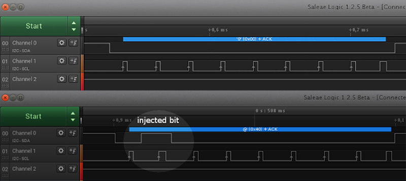
 B00011111 11111111, these addresses always roll in with three leading zeroes. The 24c512 EEPROM [Igor] is using for his hack offers 8 times as much memory, filling in the last three bits of the two-byte address space. The hack is simple: An ATtiny45 listens to the I2C bus and hears the memory address coming. By pulling the SDA line high in the right moment, the Tiny injects a three-bit memory page address that overrides the leading zeroes the firmware sends. This effectively makes one of eight 8192 bytes large memory pages (or banks) visible to the radio’s firmware. Which memory page is active can be selected through a pushbutton.
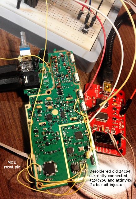
[Igor] also connected the ATtiny to the radio’s reset line to force it to re-read the memory once the memory bank has changed. Thanks to a custom boot message, which is also stored in the EEPROM, the radio even shows the selected memory bank on the LCD screen after the switching. Of course, this method isn’t limited to cheap handheld radios, it can be used to add memory banks to pretty much any device with an I2C EEPROM that does not use its entire address space. Check out the video below, where [Igor] demonstrates the trick:


I2C Bit Injection Adds Memory Banks To Everything… with an I2C EEPROM that does not use its entire address space.
Darn, and I was hoping to be able to add memory to a Speak and Spell. ;)
You were already out of luck then, somehow I doubt the TMS-1000 series of 4-bit MCUs supported I2C…
I too see, that problem
Hence the swearing…..
Woosh
On I2C the “low” is ACTIVE, the high is passive, a pullup resistor. This means you can pull an unsuspecting HIGH bit to low, but officially you cannot make a low bit high. Now… It so happens that Atmel has some of the strongest pin drivers in the industry. So as long as there is not another Atmel chip in that radio, the atmel chip will be able to override the poor CPU that’s trying to output a zero. You’re likely to exceed that CPU’s output drive capability and possibly the atmel as well.
Ah well. That’s what qualifies it as a hack… :-)
I was just wondering about this as well, wonder if this technique will eventually damage the CPU pulling the line down, guess it depends on the output impedance of the pin driving the line high. A better approach might be to proxy the I2C line between the CPU and the line, ensuring that you don’t source current that’s sinked by the CPU.
Proxying with an Atmel is not trivial. The “there is an I2C byte available” interrupt routine needs to be very fast. Clock stretching is guaranteed to work by the i2c standard (hardware supported in the atmel)….. But masters “written” for communication with a specific chip may not implement it (correctly). Examples are the BCM2835 (and -6 and -7) that has a hardware I2C implementation that is buggy when it comes to I2C clock stretching, and a software-I2C library for PIC that doesn’t support it by default. (you can turn it on as long as you have the source…)
The proxy doesn’t have to respond in perfect real-time. The Atmel could receive all the data from the CPU, then forward it after determining whether or not it’s the memory address message. If it is, it would tamper with the proper bits, sending the 0x7FFF. Every other byte could be simply repeated. It would introduce a delay, but depending on how the radio behaves, that might be acceptable.
Alternately, the chip itself could be completely replaced, with the Atmel storing the needed data instead of trying to patch the data to talk to a bigger EEPROM chip. Of course, that would cost a bit more than simple flash, but Mouser has the ATMEGA1284 with 128kb of flash for less than $8. I guarantee the time spent on this hack is worth a lot more than $8.
And I just saw Igor wrote below that this works only at speeds of 50 kHz or slower. Of course he would have thought of this! :-)
Anyway, brilliant hack, Igor!
You could probably put a low value resistor close to the target MCU and the hacking MCU will drive the I2C bus closer to the EEPROM. You could probably replace the EEPROM all together with a new MCU and put an SD card in it.
Hi Guys,
Take a look on my post (blog), there is optional resistor on the schema. I wrote that sometimes you need to add one…
Igor.
Thank God you only need 1’s and 0’s
Nice hack! I was thinking about some man-in-the-middle for more complex things: Because I2C has clock-stretching it should be possible to add a µC between main processor and let’s say some memory. Wenn the main proc makes a write request the µC processes (modifies) it if necessary and forward it to the memory. For a read request the µC can use clock stretching (pulling SCL low) to make the main proc wait, then read the memory as requested, process the data and send it back to the main proc. It could be a problem if the main proc has some very tight timeout though.
I tried this first, but without clock steching, using TWI on arduino nano @16Mhz and atmel’s at45db161 flash SPI memory. So it was like i2c eeprom inside flash spi. It worked but for very small speeds, 5-50khz, 100khz was too big. Maybe it would work using clock streching as you said and at45db161’s buffers, it has two I think. The most time consuming command was waiting for SPDR/SPSR register, but I didn’t check on which side was longer (flash confirm or master SPI).
btw. At the beginning I tried using hardware TWI slave mode to modify data, but at the end using TWI came to only sense start condition, so it was useless, but I found something cool. When you use TWI as slave and set the same address as eeprom, you will get collisions during ACK’s, but if you put diode between SDA and your TWI slave it will work. So it’s kind of cheap i2c sniffer, remember only to put data into buffer during interrupt, and extract in while() loop.
Also in this example I’m using at24c512, there is also 24c1024, but it has another ‘p’ bit inside write/read command (similar to A0..A2), so I could get even up to 16 banks in this mod.
that reset trick to display bank number is brilliant :o
Thanks! btw. I found also one additional feature on this radio + I have an idea for another mod, but I’ll do separate post for this. Currently waiting for parts to finish this one.
now this is a hack, very impressive!