[Scott Baker] wanted to take on a new retrocomputing project. He decided to build an RC2104. Lucky for us, he documented everything along the way. In addition to the main board, [Scott] built bus monitoring and debugging tools, a front panel, a real time clock, an analog to digital converter, and a speech synthesizer.
You can follow along in the 8-part post that includes videos. He started with the basic kit:
- CPU – The Z80
- ROM – 27C512 64 KB ROM, selectable in 8KB banks
- RAM – 62256 32 KB RAM
- Clock – 7.3728 Mhz crystal that drives a 74HC04 hex inverter (for the CPU and the UART)
- Serial I/O – MC68B50 UART
In addition, he picked up a digital I/O board.
The custom boards cover a wide range of functions:
- Real Time Clock (RTC) and digital output
- Bus Supervisor – A Raspberry Pi to control the bus for development
- Bus Monitor – Display address and data busses
- Front Panel – Switches and LEDs as an I/O device
- Single Stepper / Slow Stepper – Slow down execution (without it, the bus monitor isn’t very useful)
- Speech Synthesizer – A 1980s-style voice using a SP0256A-AL2
This is a great exposition of building and designing a vintage Z-80 computer. There’s a good discussion of the interfacing and bus operation. This system would have been way beyond state of the art in 1979.
We’ve talked about the RC2014 before. We’ve even covered projects using the venerable SPO256 speech synthesizer.


I had an 80s era speech synth, I used to be amused for minutes holding the W key down … Gugglegoo gugglegoo gugglegugglegugglegoo…
Heh, had the same chip… http://www.worldofspectrum.org/infoseekid.cgi?id=1000081
I built one too. My cli prompt used to say “OK” which it would pronounce “ock”. It was fun to make it say curse words.
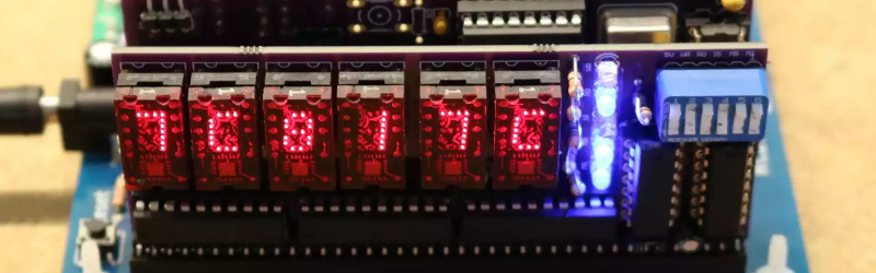
Anyone know what those display segments are called? They look cool.
Look like 5×9 dot matrix displays to me
I made a clock using them ;) til311 – they were talked about on eevblog about a year ago, more or less. a guy on ebay (portugal, iirc) has them semi-cheap.
https://c1.staticflickr.com/1/588/21117949653_8138b34cd5.jpg
Thank you!
TIL311 hexadecimal display
Was looking for these too, they look amazing
The TIL311 is only a pseudo matrix. Broadcom make the HCMS-2965 which gives you a 4 digit 5×7 matrix display for about the same cost.
there a typo on the link of first line of text. Should be RC2014 not RC2104.
I have my own typo. Should be: There is a typo …
Hey, I went my own typo too.
Me two!!
I like the RC2014 a lot and it’s a great easy build that you can get running with strip-board. I perhaps am not so fond of the harder to get chips and I don’t know why he just didn’t use FLASH instead of EPROM. Probably just to keep it authentic to the era.
EPROM is so hard to program with bits of junk lying around because of the odd voltage requirements. At least with FLASH you can stick it into a Arduino Mega and download code. Then there is the UV exposure to erase it.
I’m fairly amazed that he can get the CPU to clock at 7+ MHz on strip-board with all the parasitic capacitance and the lack of a bus terminator.
I would do much the same if the target is strip-board but the limitation of 34 strips on a strip-board and hence a bus width that has to drop signals like BUSRQ and BUSAK means that you can’t drop in a micro-controller and USB to serial bridge for code development.
I am tempted to try something similar if I loose any more sanity. 50 pin headers for the bus. Slide in cards like the old racks. All signal from the bus to other components on cards going through CPLD so solve routing issues, allow for simple upgrades or changes to configuration, and of course the glue logic and also so single sided boards can be used.
Also just to clarify – the speech chip was called sp zero two five six and not spo two five six. I see it written wrong around the net quite a lot.
Correct – SP0256
That RC2014 is a definitely a winner; it seems like it showing up everywhere lately. I would make a few improvements though: edge connectors to keep the plugin boards cheaper, and an easy-to-program microcontroller to simulate the ROM instead of dabbling with EPROM or EEPROM. I’m thinking of making one with a 65C02.
The main bus connector is just single row pin headers and you can’t get cheaper than that. It all grew out of strip-board so you can make it single sided.
For ROM, I thought FLASH would be best but live programming is not a thing that I can see happening because the Bus Request and Bus Acknowledge signals were discarded so that it all fits onto standard width strip board.
With a Propeller there are plenty of pins to monitor the address bus and control an SRAM chip. It’s fairly easy to let a Propeller bitbang the bus to let the CPU (Z80 or 6502) boot from a short program that fills the SRAM from data that the microcontroller delivers to the processor (I’ve done this in my Propeddle and L-Star projects). Then reboot the CPU and let the Propeller be a live address decoder to put the SRAM chip on the bus in read-only or read-write mode or a combination. With a Propeller, putting a binary file (e.g. a binary ROM image) into the firmware is as easy as changing a FILE command in the source code and downloading it via a (USB) serial port. I’m thinking it might even be easier if the Propeller runs software that can receive XModem, YModem or ZModem or something so you don’t have to recompile the firmware every time you want to change the ROM image.
And if you’re not familiar with the Propeller, you can probably do something similar with an ATMega 1284 or something. No EPROM erasers or special circuits required, and no long waits either.
PS: From memory the bus width of essential signals is much the same for the 6502. You can also get strip board that is wider than the common 34 or 36 strip boards.
Yeah the 6502 bus is a bit simpler than the Z80. Just a clock, a R/!W pin, 16 address bus lines and 8 data bus lines. If I recall correctly, the Z80 uses four pins to control the bus: two to read/write memory and two to read/write I/O devices. Putting a 6502 on a Z80 bus has been done before (many times) so the logic to do it is easy to find.
I have a project on Hackaday working on some ideas about a 6502 version of RC2014 but I haven’t done much so it’s private at this time. I’m thinking of using ISA bus card edge connectors, they’re ubiquitous and cheap.
ISA bus edge connectors died for a reason lol. They can’t handle dust or vibration very well. It may work with the constant re-plunging while your developing but after that you find the re-plugging may need to continue once it’s otherwise finished.
Does anybody knows which ‘modern’ chips (CPU only or MCUs) have an external parallel bus (address/data) that could replace the Z80 in this design?
I remember that some microcontrollers (like the 68HC11) could use internal or external RAM/ROM, but I don’t know if modern microcontrollers support that, given they now come with much more RAM/EEPROM/Flash than the 68HC11.
A great question and I wish I had the answer but I will offer some observations.
The Z80 is still in production as a DIP or QFP but it is 5 Volt. There is also some Z8 and Z180 micro-controllers but I am not sure what voltage they are of if the support external RAM / ROM.
There are versions of the 6502? 6802? and 68000 still in production. If there is a 3v3 version then it would be good to go with modern support chips.
The course for these chips seems to have been
1) CPU only using external peripherals, RAM, ROM, IO
2) Micro-controller that optionally can use external RAM or ROM but has peripherals and IO built in.
3) Micro-controller only with inbuilt SRAM, FLASH and has no data or address buses.
It would great if someone can answer the original quest from [replacement_cpu?] and also mention the voltage Vcc.
[Western Design Center](http://westerndesigncenter.com/wdc/) still produce 6502s, which are specified to 14 MHz at 5V and 8 MHz at 3V3
But where can you get an assembler or compiler for the Z80?
Should find something if you start here… http://www.classiccmp.org/cpmarchives/
Here’s an online assembler –
http://www.asm80.com/
I also used PASM and AS8080
The 1802, 6502, 6800, 6809, 6309, 680xx, 8080, 8085, Z80 and pretty much the entire early x86 CPU chips all have external parallel address and data busses. All are widely available for hobby use, and some are still produced in modern fast versions. You could use any of these to build something like the RC2014.
Cross assemblers for all of them are fairly easy to find. ASMX is one I’ve used. Updated versions to run on newer hardware are at .
Hrmpf: It took the links out. What the trick to include a web address in a comment? And is there a way to edit comments? I’ll try without enclosing in greater-than and less-than signs. ASMX is at http://xi6.com/projects/asmx and updates at http://www.retrotechnology.com/memship/asmx.html