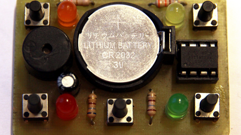
How much game can you get out of a chip with only 1 kB of flash memory and (five or) six free GPIOs? Well, you can get it to play the classic memory game, Simon. [Vojtak] is submitting this project for the 1 kB Challenge, but it looks like it’s already been used to teach simple microcontrollering to teenagers as well, so the code is actually straightforward to read, but full of nice features.
 Neat tricks include sharing button-press sensing and LED driving on the same pin, which was necessary to make everything work on such a small chip. A simple linear-congruential pseudorandom sequence provides the variation, and it’s seeded by slow-clock/fast-clock timing jitter, so you’re probably not going to see the same sequence twice. (It’s not the best random number generator ever, but it’ll do.) If that weren’t enough, high scores (and the random seed for the game) are saved to EEPROM so that you can brag to your friends or re-live your previous moments of glory.
The board is easily solderable together as well. This is a fantastic beginner project, with details in the code that everyone can learn from. It’s a great game, and a great demonstration of what you can do with a dollar’s worth of parts and 1 kB of code.

If you have a cool project in mind, there is still plenty of time to enter the 1 kB Challenge! Deadline is January 5!


This was well made and is a nice entry to the 1K contest, but an even tinier ATtiny10 simon game was featured here a few years ago: http://hackaday.com/2011/09/24/attiny-hacks-attiny10-game-doing-more-with-less/
I’m surprised it wasn’t linked somewhere above. Of course you couldn’t get as many features on that one due to fewer pins.
I have made one using a PIC10F202 in march 2012.
https://drive.google.com/file/d/0BxigE4DTzAg_RkY5eWhablJUdFdiRG5QcHV3VzI0Zw/view
all the buttons are on the same pin. they are differentiated by the time it take to charge capacitor C3 using a different
value of resistor for each button. The 4 LEDS use only 2 output pins.
source code: https://drive.google.com/file/d/0BxigE4DTzAg_QndKczhsSjlSeTJTTnRra0kxb3FfUQ/view
blog entry ( french): http://picatout-jd.blogspot.ca/2012/03/pocket-simon-avec-pic10f202.html
Is a linear congruential generator better that a linear feedback shift register or how are they different?
They are both PRNGs ( Pseudo Random Number Generator ) but are different in their implementation.
If you look at example code on the two wiki pages you can see how they differ
https://en.wikipedia.org/wiki/Linear-feedback_shift_register
https://en.wikipedia.org/wiki/Linear_congruential_generator
This page http://www.pcg-random.org/other-rngs.html has several of both with the positives and negatives listed
wow that last link is a gem! I bookmarked that thanks [MINIMAN10000] .
Thank you for a good point. I have tried LFSR and the results are really not bad. See project log: https://hackaday.io/project/18952-simon-game-with-attiny13/log/51125-testing-linear-feedback-shift-register-instead-of-linear-congruential-generator
I often use LFSR in (V)HDL (like Verilog) because it’s very easy to implement in raw logic.
Great project. I wanted to make an entry to the 1KiB competition but everyone has thought of everything already lol
I went though the micro-controller box and I was temped by some PICs cos I haven’t used a PIC for a while. I also thought about making a one bit processor in a CPLD or even a two bit if I wanted to lash out a ‘bit’ :p
Saw this project a few weeks ago. Impressive work and excellent documentation!
He might want to move those resistors for the LEDs so they’ll act as protection for the uC. Right now if you hit a button while the LED is on you can fry that port. If you move the 180ohm resistors to be between the port and the switch+led you’ll get the same ability to light the LEDs but also protect the uC’s output port from being shorted to ground.
Could have also used another (in use) GPIO for the buzzer so you don’t need the capacitor. Just keep the buzzer GPIO in sync with the other GPIO when you don’t need to ‘buzz’
The bridge connection of the buzzer requires higher input impedance than 42 ohm (probably noone manufactures them).
Surprisingly, the maximal allowed output current would not be exceeded due to high output resistance, but too much power would be uselessly converted to heat.
Not to mention there is no free GPIO.
But in that case, if you hit the switch, the LED would have no current limitation.
Best way would be to have two resistors – one in series with LED, another one in series with switch. Or in series with the pin, as you suggest.
This is a little bit commented on the project page. When the GPIO goes from input to output, the internal pullup resistor is disabled first and the GPIO is always low. The button switch is parallel to (already open) lower output transistor, so it is not dangerous for the microcontroller.
This is also used to prolong short button presses during the game (so the LED is on for at least 150 ms each time the button is pressed).