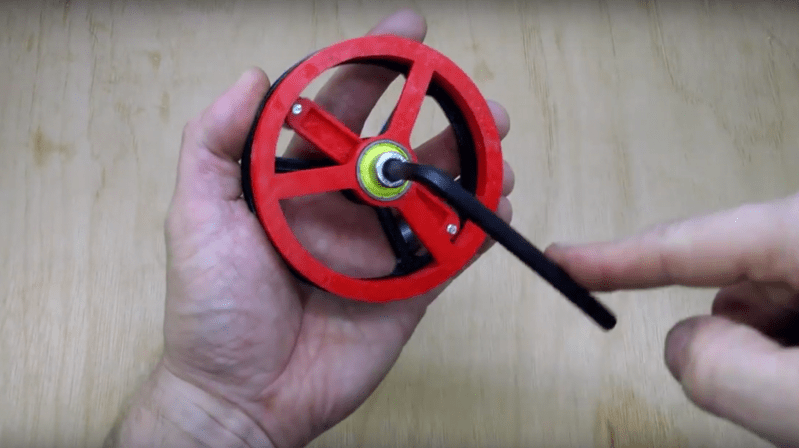
In most mechanical systems, metal gears that bend are a bad thing. But not so for strain wave gearing, which is designed to take advantage of a metal gear flexing to achieve an action much like planetary gears. The fun isn’t limited to metal anymore, though, if you 3D print a strain wave gear like this.
Strain-wave gearing is nothing new – it was invented in 1957 and has traveled to the moon on the lunar rover. And you may recall [Kristine Panos]’ recent article on a LEGO strain wave gear, which makes it easy to visualize how they work. She also has a great description of how the flex spline, wave generator, and circular spline interact, so we’ll spare those details here. [Simon Merret]’s interpretation of the strain wave gear is very simple and similar to other 3D-printed versions, except that he uses an inside-out timing belt as the flex spline. The wave generator is just an arm with a roller bearing at each end, and despite needing a few tweaks the gear does an admirable job.
Simon is reaching out for help in getting this gear ready for use where the industrial versions see frequent application – the first and second degrees of freedom of robotic arms. If you’ve got any ideas, head over to his project page on Hackaday.io and pitch in.


I am sure a lot of people would be interested in this. It’s a very cost economical 4th axis for a lot of things.
It could be made more robust by mirroring a second assembly onto a long shaft.
I am struggling getting my head round this. How does having a 300 mm long belt going all the way round differ from having two small belts, one round each bearing?
two small belts would not be linked, it would effectively reduce the speed of the axle to zero, or if friction in the bearings get too high, transmit movement at the same speed.
I can’t understand that, I still see no difference. It would work in exactly the same way.
Well you’re in luck! Print one, assemble it, and see it in action yourself.
Nothing like a working, physical model to help understand a mechanical design.
Once you have a floating belt waved by the pair of bearings, like in his second prototype, no real difference between one or two belts – they’re just a source of teeth to press against the pair of ring gears. (BTW, the ring gears mismatch in pitch and/or diameter) When you swap in the two small belts, it’s easier to think of it as split ring epicyclic gearing, except it’s driven by the planetary carrier instead of a sun.
With a classical strain wave with an ovoid wave generator, the prolonged contact of the teeth of the flexispline provides preload to minimize backlash, and spreads the load across more teeth.
At two locations 180 degrees apart the outer rotating bearings lock both of the outer disks together by pressing the belt into the grooves on each. One disk has two less grooves for the belt than the other so it will loose the space of two belt teeth in every rotation and that is the reduction ratio: ABS(Teeth2-Teeth1) / Teeth1.
If you had two separate belts they would simply move independently and the difference in the number of teeth grooves would have no effect.
Google harmonic drive. The single belt is bonded directly to the red wheel and flexes from the bearing to interact with a ring gear with a greater number of gear teeth on the black wheel. If the belts were on the bearings the they wouldn’t be connected to the red wheel, so how would power transmission take place?
Thanks for the bump Dan! All input gratefully received over on the HaD.io page linked in the article.
I’m sorry to be bitchin, but with that setup you are just not going to make anything which can be used in any practical way.
However. the concept of the harmonic drive in the vid below is pretty good adaptable to 3D printing. And with the combination of ground steel pins and plastic wheels you could get a decent amount amount of usability, torque, life expectancy, etc.
https://www.youtube.com/watch?v=MBWkibie_5I
Paul see http://reprap.org/wiki/CycloidalExtruderDrive for a DIY Cycloidal (not harmonic) drive.
Yeah, sorry, cycloidal instead of harmonic ( In harmonic / wave -gear mechanical distortion is an integral part of the gear mechanism). Cought that 5s after posting.
That Reprapped Cycloidal gear looks usable, best I’ve seen printed yet, but the concept from the Nabtesco gear is better for 3d Pinting in 2 ways:
First, Nabtesco has the steel pins on the outside circumference and the Reprap version has moving plastic on plastic, which has to transmit the total torque, which is not good for wear.
Second: The Reprapped Gearbox has a single excentric shaft in the center, while the Nabtesco has 3 in the “planet” shafts (00:02:12s in the vid). In the Nabtesco design you can use 3 (x2) ball bearings here, while there is not enough room to do that in the 12 steel pin of the Reprap version. Nabtesco has solved the problem of the small pin in a big hole here in an elegant way.
Disadvantage for 3D prining is the sun / planetary gears, which are hard to do well on a 3d printer, but these are completely on the high speed / low torque side.
Paul, no need to apologise but it’s quite a strong statement. Would you mind expanding on the reasoning behind that conclusion?
I think “used in any practical way” is pretty broad and could include educational purposes and fine rotary control of eg telescopes or cameras. Not all practical applications would need to endure high loads but until we try, we won’t really know where the limits are.
If you have a basis for saying it won’t be any use, you might save a lot of effort for the people interested in this mechanism but they would probably want to evaluate your arguments before giving up. More information please!
I’d also like more information on why it can’t be used in any practical way.
Apples and oranges.
I harmonic drive is not made to transfer high torque. The advantages of a harmonic drive are: very low back lash and high precision positioning.
And with this project you can add the advantage of cost efficiency because until now harmonic drives have been prohibitively expensive for many projects.
I might add …
I have a project here that is using 1.8 degree NEMA17 steppers with a 14:1 planetary reduction gearboxes.
That gives a full step resolution of about 2800 steps or 0.1285 degrees per full step and the backlash on the reduction gearbox’s output shaft is about 1.5 degrees or more than 10 steps of resolution.
A harmonic drive would have been ideal but they are too expensive. Something like this would have been perfect.
So now I have to find a way to deal with the backlash and non-linearity of a planetary gearbox.
Interesting concept. I’d like to see it with larger bearings so there’s more teeth in contact. The known belt tooth profile should give him several teeth in contact, but it puts the belts in shear (not the way they were made to support forces). The teeth also aren’t set up to have the same varying contact pitch, so I’m not certain if it’s getting the real backlash resistance out of it.
That’s actually one of the advantages of a conventional timing belt, the sight stretch puts teeth into opposition on the driving pulley, so that as long as you do not exceed the belt tension, it should be backlash free.
Harmonic gearboxes provide high accuracy and comparatively huge torque in a compact package. The conventional disadvantages for them is wear (the flex spline cracks from repeated stress) and they’re about 50% efficient in power transmission at best, although that means, like a high ratio worm gear, they lock up nicely. I think this design will probably have similar issues over time, replacing stress cracks with stress shearing.
Larger rotational drive systems (house sized machine tool turntables, electric mining shovels) use two motors driving a single gear. They always set up to have the reverse direction to oppose the commanded direction motor, removing backlash from the system. If you have over-torque spec’ed a stepper, a small DC motor with a constant current driver could act as a powered anti-backlash mechanism on a mechanism, guaranteeing that it would always be on one side of the tooth, within engineering limits. Placement would be critical, as the motor would have to be directly affecting the last moving mechanism on the power train (attached to an idler wheel on a belt drive, a separate pinion acting on rack and pinion, a separate drive mechanism completely for a screw drive).
I’ve done the passive version with a spring loaded coupling tying together the input shafts of two 150:1 worm gearboxes to drive a large turntable via one motor. In all cases, the losses are greater, but backlash is virtually zero if the rest of the mechanics are stiff.
Thanks for the specific insights into this mechanism and the overview of alternative approaches! I agree that a larger contact diameter at each end of the wave generator is a good plan (I use 608s on the latest version and either a larger one or a pair would be good). I *think* the low backlash might be made easier to realise because at least one of the gear rings are going to have a tooth pitch which is slightly greater or lesser than the belt.
Look up “Speed Rings” like washer’s without binding on the bearing
“Speed rings” are like washers that will not bind against the bearing
I have made a TON of Differential Planetary gearboxes and put them on Thingiverse.. actually like 5 or 6
I also do a lot of torque testing on these on my youtube channel
I am trying to prototype same design using standar steel internal gear and timing belts and standard bearings. among high ratio reducers this is the only design I can think of attempting with readily available components without 3d printing anything. Any further ideas along this line guys.