Raindrops on roses, and whiskers on kittens? They’re alright, I suppose. But when it comes down to it, I’d probably rather have a bunch of 4051, 4052, and 4053 analog multiplexers on the component shelf. Why? Because the ability to switch analog signals around, routing them at will, under control of a microcontroller is tremendously powerful.
Whether you want to read a capacitive-sensing keyboard or just switch among audio signals, nothing beats a mux! Read on and see if you agree.
The Basics
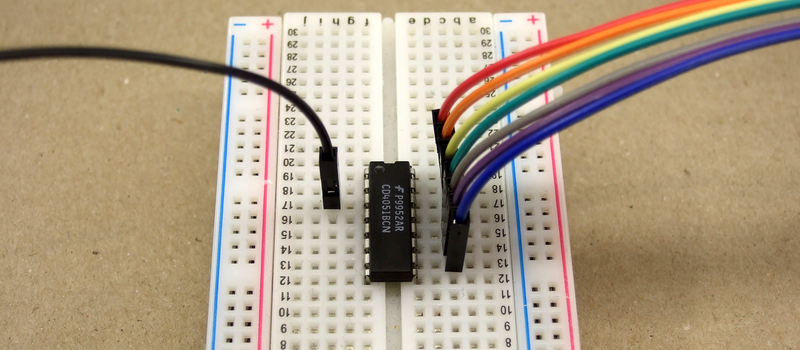
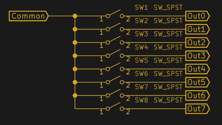 An ideal analog multiplexer routes a single common pin on one side through multiple switches to multiple pins on the other. In the case of the 4051 (an eight-way analog multiplexer) there are eight of these multiplexed switches. Close any one of the eight switches, and you’ve chosen where you’d like to send (or source) your signal.
In reality, these switches are made with transistors, and they have a non-zero on-resistance. Unlike wire-to-wire switches, the current capability of analog multiplexers is limited. But switches are opened and closed with digital logic voltages, which means that it’s a snap to put them under microcontroller control.
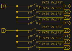
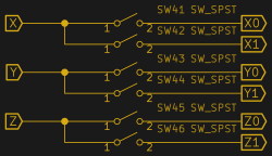
The basic trio of analog multiplexers stems from the venerable 4000-series CMOS logic chips: the 4051 is a single eight-way multiplexer, the 4052 has two four-way multiplexers, and the 4053 has three two-way switches. Despite a hefty on resistance (around 200 Ω), these chips still have their place because they’re able to switch analog signals up to twenty volts peak-to-peak, while only requiring five volt logic inputs.

The 74HC405x series chips trade off this wide voltage range for lower on-resistance and higher switching speed: passing ten-volt signals with something like 50 Ω resistance. Finally, there are low-voltage analog multiplexers meant for battery-powered use: 74LV405x run on a single-ended two volt to five volt supply and pass signals of the same size with just slightly lower on resistances.
While the various 405x series chips are a go-to of mine, you may also want to know about the 3251, 3252, and 3253 series chips: CBT3251, FST3252, SN74CBT3253, etc. They are a high-speed, low-resistance take on the same theme. They have a switching speed usually under ten nanoseconds, and resistances under ten ohms. These are actually fast enough that they can be used to make RF mixers that work up to 30 MHz.
None of these chips are meant to push significant currents, but you can get ten to twenty milliamps through most variants. They can pass signals up to roughly ten megahertz, so they’re not useful for high-frequency applications but you could use them for routing lower speed digital data in a pinch.
All of these different chips are pin-compatible across varieties, and I tend to think of them as the same thing, though you’ll want the low-voltage variety for 3.3 V projects and the old-fashioned kind for ground-referenced DC voltage signals, for instance.
Applications
If an analog multiplexer isn’t on your list of favorite things, maybe the short list of applications here will inspire you.
The most obvious use of an analog multiplexer is, um, multiplexing analog signals. A single 4052 (two four-way switches) makes a great logic-controlled source selector for your home stereo, for instance. If you have eight sources, that’s a pair of 4051s. Everyone grumbles about the ESP8266’s single ADC pin, but connecting a $0.20 74LV4051 to that single pin gives you eight choices for the ADC.
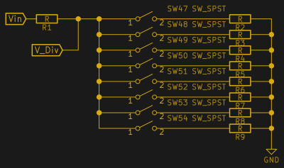
Speaking of ADCs, it’s common to need to scale up or down an input voltage range to match the ADC’s. This is often done with a pair of resistors configured as a voltage divider. Using an analog multiplexer and routing the input through up to eight different resistors can put control of the input range under control of the microcontroller in question. When the input signal is too small, the multiplexer and resistors can be used to control the gain of an amplifier. You might be tempted to use a digipot for either of these scenarios when you need more resolution, but an analog mux can get the job done in broad ranges for a lot less money.

You can make a quick-and-dirty 8×8 crosspoint switch with two 4051s by simply tying the two “commons” together. Now one of eight inputs on one side is routeable to one of eight outputs on the other. Make eight of these and you’ve got a completely flexible 8×8 routing matrix.
And then there are the niches that only an analog multiplexer can fill. For instance, you can make a simple filter with selectable cutoff frequency with a series resistor and using the multiplexer to select among multiple capacitors to ground — you can’t buy a digicap. Similarly, you can use an analog mux to pick among a set of voltage references for more precision than you could get with a digipot. If you read [Al Williams]’s piece on relay logic, you’ve doubtless got other oddball ideas about what you could do with a mux in mind.
It’s impossible to list all the cool things you can do with these chips, though, so if you have an itch that is perfectly scratched by an analog mux, tell us in the comments.


You can buy a kind of “digicap”, it’s called a Varactor.
I suppose that’s right — DAC + varactor = “digicap”. And with more than three bits of resolution to boot, though over a smaller range. Better for trimming and tuning, less so for range-switching.
(Never used a varactor, not a radio type, but it’s on my to-do list just to say I have.)
But their capacitance value rarely goes beyond a few hundred picoFarad. Good for radio frequency, not audio.
I have mentioned it before, when I connected an electric typewriter to my computer. It had an 8×8 keyboard matrix, it was easy to connect the rows and columns to two 4051. They had the common pin connected together. I connected the six control bits to a parallel port. A 4066 was used to control the shift key. Then I redirect the printer routine in the computer to my own driver. It was an Acorn Atom with built-in assembler so the development was easy. Worked well, there was of course some missing characters.
Any suggestions for a chip that works the same way but can source a higher current, like 200mA? Do those exists or will I have to use the multiplexer to switch something like a mosfet?
Not a chip but you could “do it yourself” using MOSFETs. Arrays with very low on resistance are available at low cost in small SMT packaging. You would probably also need to get high side drivers but there may low side configurations that would work for specific situations.
you can get close with ADG1606? 164-378mA continuous current depending on package, voltage and heatsink
I know, two and half years later…
I’m working on a design using the NX3L4051, which has switch currents of either 350 to 500 mA depending on wither it is constant or pulsed. Max freq of 15Mhz, a typical ON resistance of .5Ohm at VCC’s above 2V7, typical channel mismatches of .07Ohm and a charge injection of 9pC at 3V3. The only thing funky about it is a max VCC of 4V6;They spec a multitude of things at 4V3 which is a strange VCC to me(I can see 3V3 or 5V, but 4V3???).
My Korg Polysix uses one ADC and a few 4051 to read all the pots on the front.
@Elliot Williams: just a reminder. You need to check those resistors that you filed for precision values (2 months ago) and do a write up on whether their values changed.
Hey thanks! (Are we at two months already? Time flies!)
Oh wow, forgot about that. I’m interested if the humidity affected his set.
If your ok with some restrictions, like max output valtage swing of your amplifier from 0..5V, then you could have a microcontroller controlled 12Bit resolution gain amplifier using a DAC with a voltage reference input like MCP4922. GND potantial needs to be the Vss of the DAC (and microcontroller), opamp output goes to the Vref pin of the DAC and the output of the DAC to the input pin of your opamp. Amplifier can be inverting / non-inverting in design as long as the opamp output stays within allowed voltage range of the DAC. Gain can be from nearly 1 to infinity (comparator) following this formula: (2^N) / n; N = number of bits of DAC resolution; n = value send to the DAC (0 … 2^N-1);
gain example (12Bit DAC):
min: n = 0 -> (2^12)/0 = 4096 / 0 -> infinity (acts as comparator)
max: n = 4095 -> 4096/4095 = 1.000244 -> unity gain / volatge buffer
n = 2048 -> 4096/2048 = 2
n = 1024 -> 4096/1024 = 4
…
I’ve seen these used for radio direction finders. An oscillator fed to the switch swaps the receiver back and forth between two antennas at an audio frequency. When the signal source is not equidistant from both antennas, a tone is superimposed on the received audio.
Great application!
The 4067 is a 16 channel amux and perhaps more classic than the 405x mux.
I think they have stopped making them in DIP and they are only available in SOP surface mount which is a shame.
The FST3253 analog mux. is used in the Softrock-series SDR was a modulator/demodulator. Which is a clever application of a simple component.
For sure! I called it out in the article with just that application (switching mixer) in mind. I’ve even got one in the parts drawer for a “someday” radio application.
My favourite use for these is as a simple, switched capacitor circuit to convert a single channel non differential ADC into a pretty good, although slower, differential multichannel ADC.
One thing to keep in mind, when the inputs exceed the supply boundaries, the input signal bleeds through to the other channels.
You’d rather your kittens not have whiskers rather than go without analog multiplexers?!?
(c:
When you put it like that, it just sounds mean. OK, the kittens can have their whiskers.
And I’ve seen more than one momma cat chew them off…:)
Used these chips for the current sensing circuit on the brushless motor drives I used to work on at my old job. It was an older design, from the 1980s, but we still had customers using them, so we kept on supporting them, right up into 2009, when we were bought out and our location closed. Now I’m using the chips to toggle between inverted and non inverted sine waves for a synchro control transformer emulator. I’m using a DAC with the sine wave fed into the reference input as a multiplying DAC to attenuate the amplitude of the sine wave. I’ll feed the output into a modular audio driver and then through a Y wound transformer to get my isolation. I hope it works!
And it’s bidirectional. it can run as a mux 8:1 or a demux 1:8
volume, gain, treble/bass-boost(s), data-output-selector, voltage/current-regulator/driver-setting/modulation, and of course; RGB-LEDs :)
all with 4066 chips (four sets of two-terminal bi-directional analog-switches)
Aren’t these DEmultiplexers?
Depends which way you wire it, right?
So analog multiplexers have no directionality like digital ones do? That would make sense.
Actually the diagrams could’ve made that clearer. Bit pointless to write a guide to something aimed at people who already know what you’re talking about. But yep they really are a lot like switches.
Fastest I’ve seen are the 74AUC1G66 which switches about 1.8ns, outside of dedicated on-die stuff in ASICs. Anyone know of anything faster than that?
I found one of these sorts of things being used to switch resistors for range switching in a light level meter.
https://www.youtube.com/watch?v=ymUqNTDJn1g
Both of the circuits are sub-optimal. When using these as a switched gain control or divider you have the opportunity to ground the common side giving you far far greater signal to noise ratio.
These muxes are dynamite for analog synth sequencers. You can gate trigger pulses, control voltages, and analog signal sources with equal ease. If you’ve spent any brainpower trying to extend simple 4017 sequencers, consider giving up now and combining one or many 4051s with a 4516 counter as in this Ken Stone design:
https://www.cgs.synth.net/modules/cgs28_seq_switch.html
Don’t forget the 4066 on the Vic20 switching the colour ram.
There’s a 4066 in the Commodore 64 too for determining to which control port (1 or 2) the ADC in the SID chip should be connected.
Might want to rethink those circuits.
What happens to the output of the opamp at power on with all of the switches normally open?
Maybe put a resistor with the smallest or largest gain in parallel with those switches?
Maybe add a cap in parallel with that resistor to limit the bandwidth?
What happens to your divider circuit on power up with all of the divider resistors open?
Is that 12V now going into your micro?
Maybe sense the voltage on the divider resistor side of the switch?
If you have the unused peripheral, a PWM through a multi-stage low pass filter works nicely as a dac.
I had to replace a defective 4051 in the keyboard of a Xerox 820-II. About 2/3 of the keys didn’t work at all, and the rest gave mostly incorrect output.
http://q7.neurotica.com/Oldtech/Xerox/820_Keyboard1.jpg
Different 4052. The 4051/4031 you have changed is a micro-controller. The 4051 in this article is an analog switch.
Nope, this board has both an 8048 microcontroller and a 4051 mux. Note the date codes; Atmel’s AT89C4051 (an 8051 derivative) didn’t exist yet.
As spacecoyote said, it really is a 4051. Second chip in from the upper left.
Thanks for the “like” on my site!
PS: Love you web site. It’s the only place that I have seen the mark sense cards I used to use.
I’d like to know how these work internally. Are the “switches” just a pair of complementary transistors, or something like an on-chip triac?
Something like this
https://snag.gy/QmW6uw.jpg
Yes, two pairs of MOSFETs, with some clever connections around gate and bulk electrodes to achieve the wide voltages range and good isolation of inactive channels.
I used one years ago for turning pixels on and off for a NTSC video overlay. I used a synch seperator to get the veritcal and horizontal timing from a cheap camera. I used the PIC to output a pulse, black voltage or white voltage, and the 4051 was used to switch between my pulse and the pixel black/white voltage I wanted. To get the speed I needed the characters were moved 8 bits at a time in to PORTC. Then I bit shifted each which only took one cpu cycle. The lookup and move took just enough cycles that it provided great spacing for the characters. I used the font from an Apple II for my ASCII characters.
For switching high end audio I would prefer reed switches, but I am old school.
I think when you say “high-end”, you may be out of the realm of the $0.50 chip. :)
In particular, there’s real distortion in the 4051s as you get near to the power rails. It shows up in the datasheet as them having variable intrinsic resistance. I’ve never seen specs for crossover distortion, but the chips don’t run hot so there’s probably at least a little — it is made with complementary FETs on the inside.
So yeah. For desktop or “multimedia” uses, sure. But if you’re thinking about what speakers you use to listen to the sound through, those reed switches or a good mixer/preamp is the way to go.
The 4066 quad bilateral switch (very similar to these) was used to select a composite input on TV’s. They are a good choice when the data/information/base-band is encoded in the *frequency* of the signal as that is not so sensitive to distortion.
I’m working on a reverse-engineering project for DCC (Digital Compact Cassette) recorders. They use 9 tracks each direction, and there are two chips in each recorder to multiplex and de-multiplex the signals to/from the 9 heads. They work like the 4051 on steroids.
https://github.com/jacgoudsmit/DCC/blob/master/Documentation/Datasheets/TDA1380.pdf
https://github.com/jacgoudsmit/DCC/blob/master/Documentation/Datasheets/TDA1381.pdf
===Jac
At one point I had a cheap 20 channel radio shack scanner with no search function. The computer I had available to me was a VIC-20. I used 2 4051’s with the commons tied together and the 8 I/O pins of each tied to the rows and columns of the scanner keyboard. Wrote a basic program to enter the key sequence for a range of frequencies and check the state of the squelch line. It was slower than the much more expensive scanners but it did work.
Haha, I haven’t seen the word “squelch” in years! Had to think about it.
I miss the scanners loaded with crystals. Top technology back in the day…
As another interesting use case for these analog switches, I want to add “commutating bandpass filters” / “switched capacitor filters”.
I would be grateful is someone would have some understandable theory of operation :-)
A bilateral switch is just two CMOS fets that are complimentary driven so that they conduct at either polarity or direction.
Being CMOS they are ESD sensitive.
They would work fine with switched filtering. They are not meant for significant currents. They are only Small Signal devices so keep R higher and C lower in CR filters.
This is the macro for a 4066 quad bilateral switch –
http://www.ti.com/ods/images/SCHS051G/Schematic_1_SCHS051.gif
This is an oversimplification that is easier to see –
http://www.play-hookey.com/digital_electronics/images/bilateral_switch.gif
Easier to see:
[Black on Dark Grey]….
Gigglesnort
Many, many programmable-preset music synthesizers used (and still use) the 405x series. From panel reading multiplex to parameter setting demultiplex they are used in at least a hundred different machines.
I’ve been trying to feed an RF signal generated from an AD9850 DDS chip through a CD4051 demultiplexer. The output of the AD9850 is a sine wave at 1 MHz from 0 to 1 Vp-p (no negative voltage and the 4051 is running at 5 VDC). After about 20-30 seconds, the output from the 4051 dies. When I turn the power off and back on, it does the same thing over again – normal signal out then dies. I’ve ordered some high frequency, more modern version of the 4051 and hope that will cure it. Any ideas?
Is it possible to use one switch at a time by using a button to activate each switch?
It looks like Maxim got the idea and further refined it to almost perfection in MAX4734 which has 0.8Ω resistance in “on” state. But for higher price.