Multiply Your Multimeter With Relays And USB

Multimeters are a bit like potato chips: you can’t have just one. But they’re a lot more expensive than potato chips, especially the good ones, and while it’s tempting to just go get another one when you need to make multiple measurements, sometimes it’s not practical. That’s why something like this 2×4 relay-based multiplexer might be a handy addition to your bench

In this age of electronics plenty, you’d think that a simple USB relay board would be easy enough to lay hands on. But [Petteri Aimonen] had enough trouble finding a decent one that it became easier to just roll one up from scratch. His goal was to switch both the positive and negative test leads from up to four instruments to a common set of outputs, and to have two independent switching banks, for those times when four-lead measurements are needed. The choice of relay was important; [Petteri] settled on a Panasonic DPDT signal relay with low wetting current contacts and a low-current coil. The coils are driven by a TBD62783A 8-channel driver chip, while an STM32 takes care of USB duties.

The mechanical design of this multiplexer is just as slick as the electrical. [Petteri] designed the PCB to act as the cover for a standard Hammond project box, so all the traces and SMD components are mounted on the back. That just leaves the forest of banana-plug binding posts on the front, along with a couple of pushbuttons for manual input switching and nicely silkscreened labels. The multiplexer is controlled over USB using the SCPI protocol, which happily includes an instrument class for signal switchers.

We think the fit and finish on this one is fantastic, as is usual with one of [Petteri]’s builds. You’ll probably recall his calibrated current reference or his snazzy differential probe.

Sometimes It’s The Little Things

I had one of those why-didn’t-I-think-of-it moments this week, reading this article about multiplexing I2C on the ESP32 microcontroller. The idea is so good, and so simple, that it’s almost silly that it’s not standard hacker practice. And above all, it actually helps solve a problem that I’ve got. This is why I read Hackaday every day.

I2C is great in that it lets you connect up multiple devices to a pair of wires using a very bus architecture. Every device has its own address, the host calls them out, and hopefully all other devices keep quiet while just the right one responds. But what happens when you want to use a few of the same sensors, where each IC has the same address? The usual solution is to buy a multiplexer chip.

But many modern microcontrollers, like the ESP32, have an internal multiplexer setup that lets you map the pins with the dedicated hardware peripherals, usually at initialization time. Indeed, I’ve been doing it as an “init” task so long, I never thought to do it otherwise. But that’s exactly the idea behind [BastelBaus]’s hack – if you dynamically reassign the pins, you can do the I2C multiplexing with the chip you’ve got. This should probably work for any other chips that have multiple assignable pins for hardware peripherals as well.

Cool idea, but really simple. Why hadn’t I ever thought of it? I think it’s because I’ve always had this init / mainloop schema in my mind, which for instance the Arduino inherited and formalized in its setup() and loop() functions. Pin mappings go in the init section, right?

So what this hack really amounts to, for me, is a rethinking of what’s static and what’s dynamic. It’s always worth questioning your assumptions, especially when you’re facing a problem that requires a creative solution. Sometimes limitations are only in your mind. Have you had your mind opened recently by a tiny little hack?

Converting An 80s Typewriter Into A Linux Terminal

Typewriters may be long past their heyday, but just because PCs, word processor software, and cheap printers have made them largely obsolete doesn’t mean the world is better off without them. Using a typewriter is a rich sensory experience, from the feel of the keys under your fingers that even the clickiest of PC keyboards can’t compare with, to the weirdly universal sound of the type hitting paper.

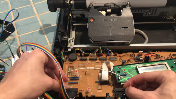
So if life hands you a typewriter, why not put it back to work? That’s exactly what [Artillect] did by converting an 80s typewriter into a Linux terminal. The typewriter is a Brother AX-25, one of those electronic typewriters that predated word processing software and had a daisy wheel printhead, a small LCD display, and a whopping 8k of memory for editing documents. [Artillect] started his build by figuring out which keys mapped to which characters in the typewriter’s 8×11 matrix, and then turning an Arduino and two multiplexers loose on the driving the print head. The typewriter’s keyboard is yet used for input, as the project is still very much in the prototyping phase, so a Raspberry Pi acts as a serial monitor between the typewriter and a laptop. The video below has a good overview of the wiring and the software, and shows the typewriter banging out Linux command line output.

For now, [Artillect]’s typewriter acts basically like an old-school teletype. There’s plenty of room to take this further; we’d love to see this turned into a cyberdeck complete with a built-in printer, for instance. But even just as a proof of concept, this is pretty great, and you can be sure we’ll be trolling the thrift stores and yard sales looking for old typewriters.

Continue reading “Converting An 80s Typewriter Into A Linux Terminal”

Mechanically Multiplexed Flip-Dot

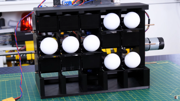
Flip dots displays are timeless classics, but driving the large ones can quickly turn into a major challenge. The electromagnets require a lot of current to operate, and the driver circuits can get quite expensive. [James Bruton] wanted to build his own, but followed a bit of a different route, building a mechanically multiplexed flip dot (ball?) display.

Each of the dots on [James]’ 5×3 proof of concept is a bistable mechanical mechanism that can either show or hide a ping pong ball sized half sphere. Instead of using electromagnets, the dots are flipped by a row of micro servos mounted on a moving carriage behind the display. The mechanism is derived from one of [James]’ previous projects, a mechanical multiplexer. Each dot mechanism has a hook at the back of the mechanism for a servo to push or pull to flip the dot. A major disadvantage of this design is the fact that the servo horn must match the state of the dot before moving through the hook, otherwise it can crash and break something, which also reduces the speed at which the carriage can move.

This build was just to get a feel for the concept, and [James] already has several ideas for changes and improvements. The hook design can certainly change, and a belt drive would really speed things up. We think this mechanical display is a very interesting design challenge, and we are interested to hear how our readers would tackle it? Let us know in the comments below.

Recently we covered a 3D printed flip dot display for the first time. It’s still small and [Larry Builds] is working out the kinks, but we would love to see it eventually match the mesmerising effect of Breakfast’s large installations.

Image Sensor From Discrete Parts Delivers Glorious 1-Kilopixel Images

Chances are pretty good that you have at least one digital image sensor somewhere close to you at this moment, likely within arm’s reach. The ubiquity of digital cameras is due to how cheap these sensors have become, and how easy they are to integrate into all sorts of devices. So why in the world would someone want to build an image sensor from discrete parts that’s 12,000 times worse than the average smartphone camera? Because, why not?

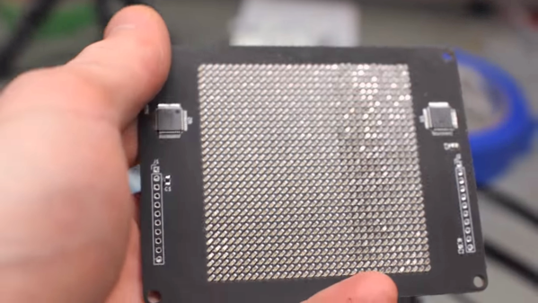
[Sean Hodgins] originally started this project as a digital pinhole camera, which is why it was called “digiObscura.” The idea was to build a 32×32 array of photosensors and focus light on it using only a pinhole, but that proved optically difficult as the small aperture greatly reduced the amount of light striking the array. The sensor, though, is where the interesting stuff is. [Sean] soldered 1,024 ALS-PT19 surface-mount phototransistors to the custom PCB along with two 32-bit analog multiplexers. The multiplexers are driven by a microcontroller to select each pixel in turn, one row and one column at a time. It takes a full five seconds to scan the array, so taking a picture hearkens back to the long exposures common in the early days of photography. And sure, it’s only a 1-kilopixel image, but it works.

[Sean] has had this project cooking for a while – in fact, the multiplexers he used for the camera came up as a separate project back in 2018. We’re glad to see that he got the rest built, even with the recycled lens he used. One wonders how a 3D-printed lens would work in front of that sensor.

Continue reading “Image Sensor From Discrete Parts Delivers Glorious 1-Kilopixel Images”

3D Print Your Way To A Glass Cockpit Simulator

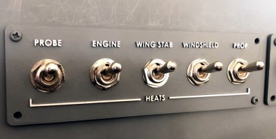
Today’s commercial aircraft are packed to the elevators with sensors, computers, and miles and miles of wiring. Inside the cockpit you’re more than likely to see banks of LCDs and push buttons than analog gauges. So what’s that mean for the intrepid home simulator builder? Modern problems require modern solutions, and this 3D printed simulator is about as modern as it gets.

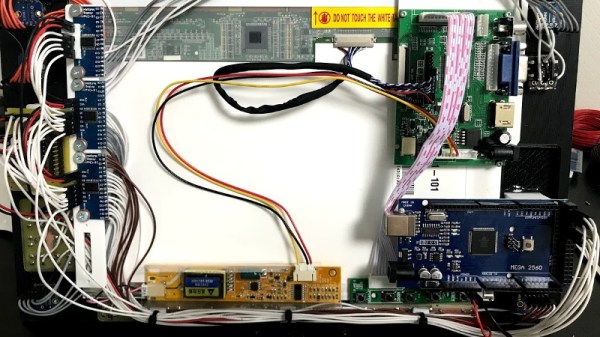
Published to Thingiverse by the aptly named [FlightSimMaker], this project consists of a dizzying number of 3D-printed components that combine into a full-featured desktop simulator for the Garmin G1000 avionics system. Everything from the parking brake lever to the push buttons in the display bezels was designed and printed: over 200 individual parts in all. Everything in this X-Plane 11 compatible simulator is controlled by an Arduino Mega 2560 with the SimVim firmware.

To help with connecting dozens of buttons, toggle switches, and rotary encoders to the Arduino, [FlightSimMaker] uses five CD74HC4067 16-channel multiplexers. The display is a 12.1 inch 1024 x 768 LCD panel with integrated driver, and comes in at the second most expensive part of the build behind the rotary encoders. All told, the estimated cost per display is around $250 USD.

Even if you aren’t looking to build yourself a high-tech flight simulator, there’s plenty of ideas and tips here that could be useful for building front panels. We particularly like the technique used for doing 3D-printed lettering: the part is printed in white, spray painted a darker color, and then the paint is sanded off the faces of the letters to reveal the plastic. Even with a standard 0.4 mm nozzle, this results in clean high-contrast labels on the panel with minimal fuss.

Of course, while impressive, these panels are just the beginning. There’s still plenty more work to do if you want to build an immersive simulation experience. Including, in the most extreme cases, buying a Boeing 737 cockpit.

Turning OLEDs And Acrylic Into Faux Nixie Tubes

Love ’em or hate ’em, Nixies and the retro clocks they adorn are here to stay. At least until the world’s stock of surplus Soviet tubes is finally depleted, that is. The glow discharge tubes were last mass manufactured in the 1980s, and while they’re not too hard to get a hold of yet, they will be eventually. And what better way to get ready for that dreaded day than by rolling your own OLED faux Nixie tubes?

Granted, [Derek]’s faux Nixies, appropriately dubbed “Fixies,” require just a touch of willing suspension of disbelief. We’ve never see Nixies with tiny jam jars as envelopes, so that’s probably the first giveaway. But looking past that, the innards of these fake displays do a pretty convincing job of imitating the texture of the real thing.

The numbers themselves are displayed on a 128×64 white OLED display using a Nixie-like True Type font. An orange acrylic filter in front of the display gives it that warm amber Nixie glow, with laser etchings mimicking both the fine hexagonal anode grid and the ghostly cathodes of the non-illuminated numerals. The tubes looked convincing enough that a clock was in order, and after sorting through an I2C bottleneck with the help of a multiplexer, [Derek] had a pretty decent faux-Nixie clock, complete with a solenoid-actuated mechanical gong. The double-digit display for the seconds will no doubt cause some consternation among Nixie purists, but that’s probably part of the fun.

Of course, just because Nixies aren’t being mass-produced today doesn’t mean you can’t get new ones. You just have to be willing to pay for them, and [Dalibor Farný] will gladly set you up with his handmade artisanal Nixies, or even a clock kit using them.

Continue reading “Turning OLEDs And Acrylic Into Faux Nixie Tubes”