A few weeks ago, I was working on a small project of mine, and I faced a rather large problem. I had to program nearly five hundred badges in a week. I needed a small programming adapter that would allow me to stab a few pads on a badge with six pogo pins, press a button, and move onto the next badge.
While not true for all things in life, sometimes you need to trade quality for expediency. This is how I built a terrible but completely functional USB to serial adapter to program hundreds of badges in just a few hours.
This is not the right way to do this.
As is usually the case for any tutorial I write, this is not the right way to do things. In commercial or manufacturing settings, pogo pins are usually found in test or programming jigs. In these jigs, the pogo pin is mounted perpendicular to a PCB, with each pin running through a second identical PCB mounted on standoffs. Just look at these fantastic products on Tindie for an example. These two PCBs provide mechanical stability and electrical connections to each pogo pin. This is a very robust system, but building one of these test jigs means I need to order a few PCBs. I didn’t have the time to do this, so I needed another solution.
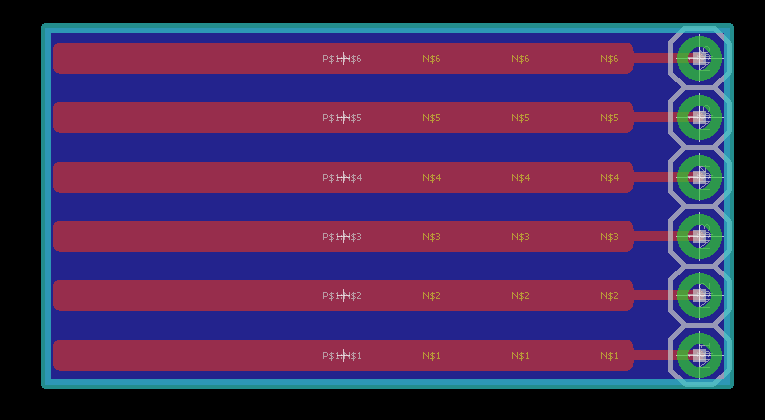
All I need is some way to hold six pogo pins on 0.1″ centers, with a few pads to wire these pins up to a USB to serial adapter. A single PCB to do this is extremely simple — all you need are a few pads to hold the pogo pins and a set of holes to plug a serial adapter into.
I managed to whip up a PCB (right) for this in about three minutes. It’s extremely simple, with the only remarkable feature being six very long pads for the pogo pins. If you’re very good at applying solder paste by hand, the surface tension of melted solder will align the pogo pins, leaving you with six perfect pogo pins all aligned and parallel to each other.
A PCB solution is easy, but it also takes time. Unless you have a PCB mill sitting in your lab, you’ll have to make due with ordering this board from OSH Park or something. Sometimes you need a pogo pin programmer right now.
If you don’t have a PCB mill, I hope you have a 3D printer. Last year, [Timothy Reese] created the Fiddy for Adafruit. This is a 3D printed ‘clip’ for six pogo pins, designed to clip onto the end of an Adafruit Pro Trinket for FTDI programming. Before designing my own pogo pin adapter, I made Fiddy. It performs its job well. The Adafruit Fiddy will clamp down on small boards, and it will program them.
There are a few shortcomings to the Adafruit Fiddy. I found my 3D printed version to be a little too flexible, although this is probably because I printed it in ABS, not PLA. The Fiddy is a little bulky. I also don’t need a programmer that clamps down on a board — I’m more than happy to hold a serial programmer against a board for forty-five seconds if it means the pins are a little more secure and the device is a little more robust.
Here’s what I did
There’s the lit review for the existing solutions for a simple, handheld pogo pin programmer. They’re all good, but I needed something right away. Except for the pogo pins (available wherever fine electronics are sold), I only needed a few items that were already on my workbench:
- 30 AWG Kynar wire
- 5-minute epoxy
- Solder
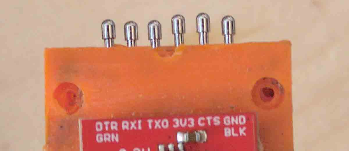
- Any random “FTDI” USB to serial converter
For this project, the pogo pins will be held in place with a 3D printed adapter. After a few minutes in OpenSCAD, I came up with this model. It aligns six pogo pins on 0.1″ centers, and can be epoxied to the back of a standard, off-the-shelf USB to Serial adapter.
module pins(){
  for (a=[2.54:2.54:15.24]){
    translate([0,a,-0.01])
    cylinder(d=1.45,h=21, $fs=0.01);
  }
}

module front(){
  difference(){
    cube([2,17.78,20]);
    pins();
  }
}

module back(){
  difference(){
    translate([-4,0,0])
      cube([4,17.78,20]);

    translate([-5,0,0])
      cube([3,17.78,4]);

    translate([-5,6.5,0])
      cube([3,4,21]);

    pins();
  }
}
 There’s not much to this 3D printed pogo pin adapter. Think of these 3D printed parts as more of a jig, with a small amount of epoxy providing the mechanical strength.
These parts were printed at a very low layer height (0.05mm) using whatever filament was already in my printer. The orientation of the parts on the bed required support for the overhangs that would become the space behind the normal FTDI pin headers, and a passthrough for the Kynar wire from the pins to the pads.
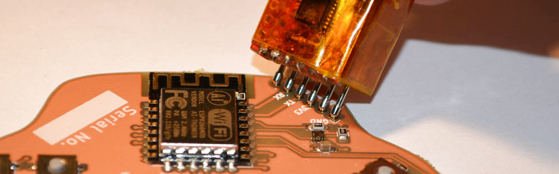
In normal applications of pogo pins, you’d simply place the pin in a circular pad and solder the brass casing to a PCB. I don’t have this option, so I need to attach Kynar wire. I did this by stripping the Kynar, placing 2-3 millimeters of stripped wire in the hole at the non-pogo end of the pin, tacking it down, and wrapping the rest of the stripped wire around the pin. A tiny bit of solder holds everything together, and a small bit of heat shrink will keep the pins from shorting to each other once this is assembled.
After preparing six pogo pins, I had to sandwich all of them between two pieces of plastic. If I have one tip on how to do this, it’s, ‘go slow’. I used five-minute epoxy for this, installing one pin at a time and making sure they were all aligned and even. It takes patience, but it will work.
After that, the only thing left to do was to solder the other end of the Kynar wire to the FTDI adapter. It’s small, fiddly soldering, but it can be done.

Did it work? Yes. Is it good? Ehhhh….
While I was able to program a few hundred badges with this pogo pin serial adapter, I’m not going to call this a ‘good’ solution. There are a few issues with this device, and I’m actually surprised it worked in the first place.
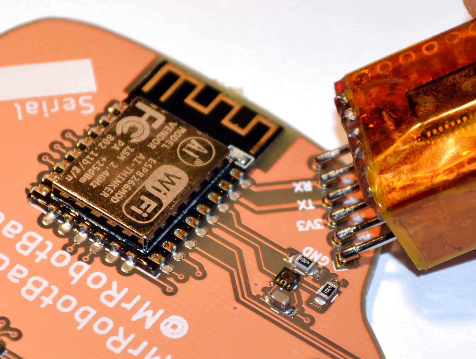
After programming, the ESP8266 on the badge restarts, and the LEDs turn on. While the power supply for the FTDI adapter is capable of providing the required ~300mA to the badge, I should have used a larger gauge wire to attach the pogo pins to the USB to serial adapter. This really isn’t a big issue, but it is an issue.
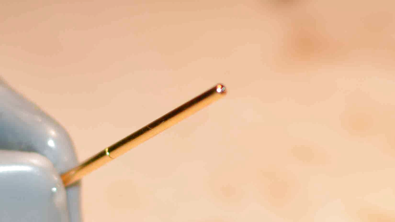
Additionally, I had to be very, very careful not to get any epoxy on the ‘springy’ part of the pogo pins. It’s easy to not screw up the springiness of pogo pins if you’re dealing with solder, but epoxy gets everywhere. I found that a quick rub down with isopropyl alcohol does clean the pins, but this is still something I wish I didn’t have to deal with.
If I had to do this again, with no limitations on time or money, I would take the PCB I created in Eagle above, grab an FTDI chip and a USB connector, and simply build my own USB to serial adapter that uses pogo pins instead of pin headers. This actually wouldn’t be that much work — two hours to design the circuit, maybe an hour assembling it, and if everything goes right I’d have the perfect tool for the job.
However, sometimes you just have to solder and glue some crap together and hope it works. That’s what I managed to do here, and yes, it did work.


Obvious improvement would be to have a channel part-length alongside the popo pins. Normal wire can then be soldered well to the body of the pogo pin easily
No need for anything 3d printed with pogo pins, try DIL/SIL headers (available in various orientations), and if you want them on a fly-lead, they can also be jammed into the end of most panel sockets (it’s what I currently have for programming a number of boards that only have test-pads for access to the programming header).
You might need to fine-tune the sizes to get a snug fit without too much variation at the end of the pogo-pins but, after a decent press, they should all be aligned (I’d also highly recommend using sharp-point pins, going in to through-hole/vias rather than what I did which was surface test-pads that provide no positive locating effects).
Oh, the other thing I’d suggest (that I forgot about), if you don’t have a fixed jig that ensures orientation, make it clear which way around the header goes on, either via a silk-screen (that matches with labels on the adapter) or by making the connection polarised (asymmetric pin spacing or having a shape, such as a T or L).
For me at least, it’s easy to get hung up on making things look nice, even when that is not a requirement.
Hopefully next time I’ll remember “…sometimes you just have to solder and glue some crap together and hope it works”.
Hmm, if that is standard 0.1″ pin spacing then just cutting two pieces of veroboard/stripboard to hold the pogos would have been enough. Probably 10x faster to build and more robust to boot.
And what is this nonsense about having to order boards – etching a simple board like this using toner transfer (even though not required if the above works) is about an hour of work including drilling it.
Sometimes the engineer is his/her own worst enemy by overthinking things.
Ask amateur mechanics. Most things that are “about an hour” take the better part of a day if you aren’t familiar with the technique or prepared with materials on hand.
Hofstadter’s Law: It always takes longer than you expect, even when you take into account Hofstadter’s Law
I did something similar using milled PCBs, see here:
https://trochilidae.blogspot.co.uk/search?q=pogo
Maybe a break-away edge-connector with a test plane interface would be better.
We do this for large panels of programmable parts when the supplier doesn’t allow custom code lots (handy to use a USB boot-loader).
Also, plated through-holes allow long .1″ spaced pin strips to contact well when inserted and pushed sideways 45′ (the PCB plating is badly marred, but it does work reliably.)
A 3D printed cradle with a hinge, made specifically for the board to be tested/programmed, can speed things up many times while working with pogo pins.
I made several designs using this method (test fixture for populated PCBs), but also built one from machined delrin, pogo pins and a de-sta-co clamp to program a PCB design.
i use piano wire in a IDC header, it has just enough spring when held at a angle.
Or you could use a :
http://www.tag-connect.com/
And add a 2×5 .1″ header to your PCB or flywire off a bridge board?
Tag Connect FTW. Sure, there’s tons of DIY options and they certainly can be cheaper (if your time is free) but tag connect is very compact and reliable production gear. I love it :)
Add a small piece of perfboard as spacer
Push back of pogo pins all the way back on breadboard.
Solder
Perfectly aligned.
http://i.imgur.com/msprgIg.jpg
oops, imaged dead. Try a new one
http://i.imgur.com/EBzNV5a.jpg
Regular old .1″ pin headers can work well enough for this purpose. Modelers have been using them for years to program ESCs. They have just enough flex to make contact when pressed down sideways. There are also spring pins available that are preassembled into rows like this. It’s not something we have just lying around, but it’s a really good solution in the long run,
This. Ribbon cable with make DuPont connectors on the programming end is what I use, works flawlessly.
You know there are receptables/sockets for pogopins? i.e. the R100-xW, R100-xS or R100-3T here: http://dirtypcbs.com/store/designer/details/ian/12/dirty-pogo-pins They come in wirewrap (or directly solderable in a PCB) or crimp. This is how the professional testrigs are made of..
Those have advantages over soldering the wire to the pogopin directly:
– solder won’t interfere with the inner workings of the pogopin (i.e. stuck to the spring inside)
– pogopins are easily replaced (they are only rated upto about 1K compressions)
– can be crimped
Wrote a post about programming adaptors (and pogopin receptables) here using PCB instead of 3D printing: http://SMDprutser.nl/blog/diy-programming-adapters/
Ages ago, I did this with hot glue. Placed the pogo pins on tape, gooped hot glue over them, turn over remove tape, hot glue on the other side, done. Still use the adapter once in a while. Originally I didnt have proper pogo pins, i used the pins and parts of an old lock that would behave like a pogo pin.
Hot glue is great for “molding” quick parts that need to be a bit flexible and tolerance doesnt need to be that accurate.
or do an edge connector on the side of the board, and use the ribbon style idc to mate too it.
FDM and pogo pins are great for making debug interfaces for off-the-shelf stuff.
I did this for the Hubsan Q4 micro quadcopter (shameless project plug):
https://hackaday.io/project/4751-bradwii-on-the-hubsan-q4
https://www.thingiverse.com/thing:652613
I just built one of these for an ESP-12 yesterday — ethanmye.rs has my writeup, and youtube has a short video about it. https://youtu.be/3vYy9TrM9Js
Actually, who was it? Tecuci? Don’t engineer a thing to last forever if it only needs to last 6 months. I believe he wrote several books on Life cycle and replacement engineering for manufacturing. They applied it to cars and aircraft in the U.S. in the 80’s and onward. Used for things like tool replacement and other items that need to be replaced over a statistical period of time. One I can think of is aircraft lights, so many hours and they replace them regardless of if they are burned out. It works in electronics too I guess.
What types of pin heads go with what? (Pin heads, haha.) I see many varieties. Is there some guide? I couldn’t find one.
https://www.google.com/search?q=pogo+pin&source=lnms&tbm=isch&sa=X&ved=0ahUKEwj1vsH9or7VAhWEw4MKHWRACmYQ_AUICigB&biw=1366&bih=702#imgrc=_
take a look here: http://dirtypcbs.com/store/designer/details/ian/12/dirty-pogo-pins
scroll down for which pogo pin is used in which situation.
In my experience, 5 minute epoxy is NOT what you want to use if you want to “go slow”
Epoxy working time seems to be measured in snooze alarm minutes, not in microwave timer minutes.
Use epoxy with a longer working time. I just wish there was something between 5 min & 1hr, which are the two I commonly see at the hardware store.
Throw it in the fridge. Voila. 10 minute epoxy. ;)
I was working on a project recently at work where the hardware was finalized but the software was not. I made a 2 x 6 header footprint for the board with the pins slightly off-center from one another. This allows for a friction fit with a male header for the ISP IDC connector but allows it to be removed when finished. I was surprised it lasted for so long (30-40 connect/disconnect cycles) with no connection issues.
Sounds like the scheme SparkFun uses: https://www.sparkfun.com/tutorials/114
Yes. Yes I do have an idea of how annoying those misaligned pins are.
But perfection doesn’t come on the Mark I model. That usually doesn’t start until Mark 93.
Have a look at the programmer shown as part of this project:
https://hackaday.io/project/25826-yet-another-fidget-pov-yafpov
Uses a spring contactor designed for flexible cable, along with a 3D printed spacer with a locating notch. Simple and cheap. I use it as an AVR programmer, but it could be a serial connector as well.
That is an elegant solution.
I would think a PCB hole or two and matching pins would help with alignment. Then this could be more easily used on multiple projects.
I may not have made it clear, but I put a locating notch into the target circuit board and a matching tab on the spacer. This turns out to position the connector very repeatably.
Use probe/pogo pin receptacles.
They mate with pogos and the leads are solderable/wirr wrapped.
Someone probably mentioned it, but did you know that you can just buy pogopins (spring loaded pins) in standard 2.54mm pitch, readily assembled? I bought a couple from Mouser and used in a similar programmer. Just search for spring loaded pin at Mouser and select your pitch and number of contacts. You then just solder cables to it (or directly to your PCB, if that’s what you prefer).
It looks like you would still have to hold it in place by hand while it programs.
My first thought was that I would just have designed it to work with a Prop Clip. https://www.parallax.com/sites/default/files/downloads/32201-Prop-Plug-Documentation-v1.3.pdf
That would be kind of nice because it just clips on the edge of the board. Unfortunately that is only a UART interface. You would have to already have a bootloader on the chip.
Maybe it would be possible to make something like what you have but put the pogo pins at right angles to the case. Then glue the whole thing to a clothes pin so that you can just clip it onto your board.
Hi there,
We have created a pogo header clamp which you may like :
https://www.kickstarter.com/projects/1250664710/pcb-quick-connect-clip-40-pin-raspberry-pi-compati?ref=piforumpogo
It lets you connect from 1 to 40 pins in a header, as simple as clamping the PCB !
Matt