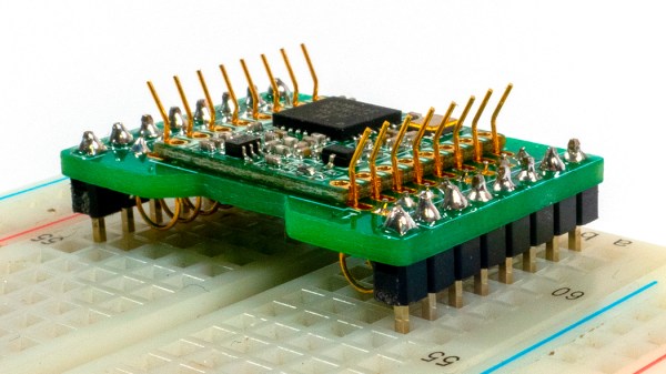
RFM9x module held in an adapter board with flexipins

FlexyPins Might Help With Those Pesky Castellated Modules

[SolderParty] just announced FlexyPins (Twitter, alternative view) – bent springy clips that let you connect modules with castellated pins. With such clips, you can quickly connect and disconnect any castellated module, swapping them without soldering as you’re prototyping, testing things out, or pre-flashing modules before assembly. They’re reportedly gold-plated, and a pack of ~100 will set you back 6EUR, shipping not included.

Of course, this is basically “fancy pieces of wire”, purpose-shaped, gold-plated and, hopefully, made out of material that is springy enough and doesn’t snap easily after bending a few times. We’ve seen this concept used for prototyping before, with random pieces of wire doing a pretty good job of maintaining connectivity, but these clips bring it that much closer to production-grade. It also makes us wonder – just how hard it is to solder 30-40 of them into a circuit? Do they self-align enough with the footprints given, or do you have to hold them with tweezers at a peculiar angle as you solder them? Time will tell, of course.

Continue reading “FlexyPins Might Help With Those Pesky Castellated Modules”

Production PCB And Pogo Pins Produce A Clever Test Jig

[Hans Summers] runs a site qrp-labs.com, selling self-assembly kits mostly for radio gear and GPS applications, and had some production problems with his QCX-mini QRP transceiver kit. They were using an assembly house that had some problems with a sub-contractor going under during the pandemic, and the replacement service was somewhat below the expected level of quality, resulting in a significant number of SMT populated boards coming out non-functional. Obviously, not wanting to pass these on to customers as a debug problem, they set to work on an in-house QA test jig, to give them the confidence to ship kits again. The resulting functional test jig, (video, embedded below) takes a fairly interesting approach. Skip the video to 9:00 for the description of the test jig and detailed test descriptions.

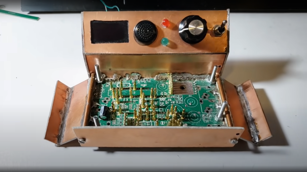
By taking an existing known-good PCB, stripping off all the SMT parts, and moving the through hole components to the rear PCB side, pogo pins could be soldered to strategic locations. Building the assembly into a rudimentary enclosure made from sawn-up raw copper clad board, with the pogos facing upwards, and a simple clamp on top, allowed the PCB-under-test (let’s call it the UUT from hereon) to be located and clamped in place. This compressed the pogos in order to make a firm electrical contact. A piece of MDF that had been attacked with a dremel did duty as a pressure plate, with cutouts around the SMT component areas to achieve the required uniform board pressure and keeping the force away from the delicate soldered parts. All this means that with an UUT connected via pogo pins to a through-hole only test PCB, the full circuit would be completed, if and only if the UUT was completely functional, and that means defect-free soldering and defect-free components.

Next the firmware was rewritten to do duty as the test controller, which when powered up would step through a sequence of test scenarios and measurements, logging the results to an OLED display and a serial interface. This rig survived 1,000 SMT tests without failing, giving [Hans] the confidence to ship out new kits and providing a database of datalog results as a backup should a customer have an issue during final assembly. All-in-all a smart idea to solve a difficult problem, with nary a custom test jig PCB in sight!

These pages have been graced with many a pogo-based test rig over the years. Here’s one to start, and if you’ve got a handy laser cutter and some scrap wood, making an accurate test rig is no bother either.

Continue reading “Production PCB And Pogo Pins Produce A Clever Test Jig”

SMART Response XE Turned Pocket BASIC Playground

Ever since the SMART Response XE was brought to our attention back in 2018, we’ve been keeping a close lookout for projects that make use of the Arduino-compatible educational gadget. Admittedly it’s taken a bit longer than we’d expected for the community to really start digging into the capabilities of the QWERTY handheld, but occasionally we see an effort like this port of BASIC to the SMART Response XE by [Dan Geiger] that reminds us of why we were so excited by this device to begin with.

This project combines the SMART Response XE support library by [Larry Bank] with Tiny BASIC Plus, which itself is an update of the Arduino BASIC port by [Michael Field]. The end result is a fun little BASIC handheld that has all the features and capabilities you’d expect, plus several device-specific commands that [Dan] has added such as BATT to check the battery voltage and MSAVE/MLOAD which will save and load BASIC programs to EEPROM.

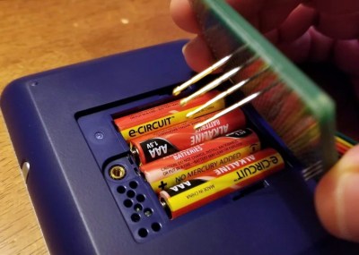
To install the BASIC interpreter to your own SMART Response XE, [Dan] goes over the process of flashing it to the hardware using an AVR ISP MkII and a few pogo pins soldered to a bit of perboard. There are holes under the battery door of the device that exposes the programming pads on the PCB, so you don’t even need to crack open the case. Although if you are willing to crack open the case, you might as well add in a CC1101 transceiver so the handy little device can double as a spectrum analyzer.

Continue reading “SMART Response XE Turned Pocket BASIC Playground”

Transforming Work Light Is More Than Meets The Eye

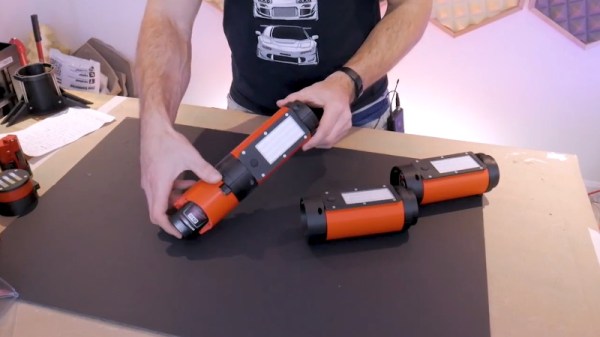
While it does use the same M12 batteries, this impeccably engineered work light isn’t an official Milwaukee product. It’s the latest creation from [Chris Chimienti], who’s spent enough time in the garage and under the hood to know a thing or two about what makes a good work light. The modular design not only allows you to add or subtract LED panels as needed, but each section is able to rotate independently so it points exactly where you need it.

Magnets embedded in the 3D printed parts mean the light modules not only firmly attach to one another, but can be stuck to whatever you’re working on. Or you could just stack all the lights up vertically and use the rocket-inspired “landing legs” of the base module keep it vertical. Even if the light gets knocked around, the tension provided by rubber bands attached to each fold-out leg means it will resist falling over. In the video after the break [Chris] says the little nosecone on top is just for fun and you don’t have to print it, but we don’t see how you can possibly resist.

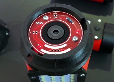
The same PCB is used on both ends of the light modules.

Of course, 3D printed parts and magnets don’t self-illuminate. The LED panels and switches are salvaged from cheap lights that [Chris] found locally for a few bucks, and a common voltage regulator board is used to step the 12 volts coming from the Milwaukee battery down to something the LEDs can use. He’s designed a very slick reversible PCB that’s used on either end of each light module to transfer power between them courtesy of semi-circular traces on one side and and matching pogo pins on the other.

As we saw in his recent Dremel 3D20 rebuild, [Chris] isn’t afraid to go all in during the design phase. The amount of CAD work that went into this project is astounding, and serves as fantastic example of the benefits to be had by designing the whole assembly at once rather than doing it piecemeal. It might take longer early on, but the final results really speak for themselves.

Continue reading “Transforming Work Light Is More Than Meets The Eye”

This Debug Connector Brings Your Issues To The Edge

Given an unknown PCBA with an ARM processor, odds are good that it will have either the standard 10 pin 0.05″ or 20 pin 0.1″ debug connector. This uncommon commonality is a boon for an exploring hacker, but when designing a board such headers require board space in the design and more components to be installed to plug in. The literally-named Debug Edge standard is a new libre attempt to remedy this inconvenience.

The name “Debug Edge” says it all. It’s a debug, edge connector. A connector for the edge of a PCBA to break out debug signals. Card edge connectors are nothing new but they typically either slot one PCBA perpendicularly into another (as in a PCI card) or hold them in parallel (as in a mini PCIe card or an m.2 SSD). The DebugEdge connector is more like a PCBA butt splice.

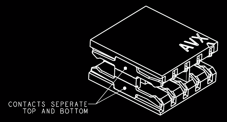
It makes use of a specific family of AVX open ended card edge connectors designed to splice together long rectangular PCBAs used for lighting end to end. These are available in single quantities starting as low as $0.85 (part number for the design shown here is 009159010061916). The vision of the DebugEdge standard is that this connector is exposed along the edge of the target device, then “spliced” into the debug connector for target power and debug.

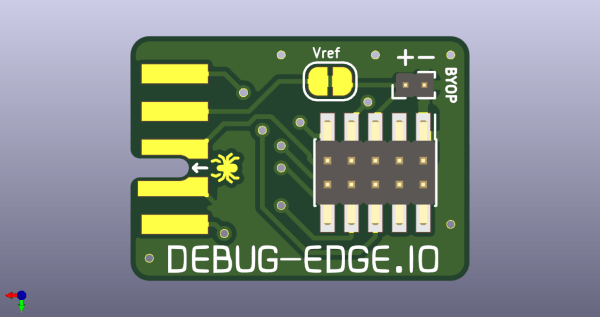
Right now the DebugEdge exists primarily as a standard, a set of KiCAD footprints, and prototype adapter boards on OSHPark (debugger side, target side). A device making use of it would integrate the target side and the developer would use the debugger side to connect. The standard specifies 4, 6, 8, and 10 pin varieties (mapping to sizes of available connector, the ‘010’ in the number above specifies pincount) offering increasing levels of connectivity up to a complete 1:1 mapping of the standard 10 pin ARM connector. Keep in mind the connectors are double sided, so the 4 pin version is a miniscule 4mm x 4.5mm! We’re excited to see that worm its way into a tiny project or two.

We’ve seen plenty of part-free debug and programming connectors before. Have a favorite? Let us know in the comments!

A Custom Milled Jig For Smart Bulb Programming

Who would have thought that some day we’d need programming jigs for our light bulbs? But progress marches on, and as there’s currently a number of affordable Internet-controlled bulbs powered by the ESP8266 on the market, we’re at the point where a tool to help update the firmware on the light over your kitchen sink might be something nice to have. Which is why [cperiod] created this programming jig for AiLight smart bulbs.

Flashing the AiLight bulbs is easy enough, there’s a series of test points right on the face of the PCB that you can hook up to. But if you’re updating more than one of them, you don’t want to have to solder your programmer up to each bulb individually. That’s where the jig comes in. [cperiod] says there are already some 3D printed designs out there, but they proved to be a bit finicky.

The design that [cperiod] came up with and eventually milled out on a 1610 CNC router is quite simple. It’s effectively just a holder to keep the five pogo pins where they need to be, and a jumper that lets you toggle the chip’s programming mode (useful for debugging).

The neat trick here are the “alignment pins”, which are actually two pieces of 14 gauge copper wire that have had their ends rounded off. It turns out these will slip perfectly into holes on the AliLight PCB, ensuring that the pogo pins end up on target. It works well enough that you can hold the bulb and jig in one hand while programming, it just needs a little downwards pressure to make good contact.

We’ve previously seen how easily you can replace the firmware on some of these ESP8266 bulbs. While there’s certainly a downside to these bulbs being so simple to modify, it’s hard to deny their hackability makes them very appealing for anyone looking to roll their own network-controlled lighting system.

Magnetic Attraction Of Microduino MCookie Modules

We’ve seen countless different robot kits promoted for STEM education, every one of which can perform the robotic “Hello World” task of line following. Many were in attendance at Maker Faire Bay Area 2019 toiling in their endless loops. Walking past one such display by Microduino, Inc. our attention was caught by a demonstration of their mCookie modules in action: installing a peripheral module took less than a second with a “click” of magnets finding each other.

Many Arduino projects draw from an ecosystem of Arduino shields. Following that established path, Microduino had offered tiny Arduino-compatible boards and peripherals which connected with pins and headers just like their full-sized counterparts. Unfortunately their tiny size also meant their risk of pin misalignment and corresponding damage would be higher as well. mCookie addresses this challenge by using pogo pins for electrical contacts, and magnets to ensure proper alignment. Now even children with not-quite-there-yet dexterity can assemble these modules, opening up a market to a younger audience.

Spring loaded electric connections are a popular choice for programming jigs, and we’ve seen them combined with magnets for ideas like modular keyboards, and there are also LittleBits for building simple circuits. When packaged with bright colorful LEGO-compatible plastic mounts, we have the foundation of an interesting option for introductory electronics and programming. Microduino’s focus at Maker Faire was promoting their Itty Bitty Buggy, which at $60 USD is a significantly more affordable entry point to intelligent LEGO creations than LEGO’s own $300 USD Mindstorm EV3. It’ll be interesting to see if these nifty mCookie modules will help Microduino differentiate themselves from other LEGO compatible electronic kits following a similar playbook.