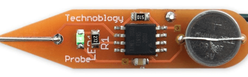
There’s an inside joke among cyclists – the number of bikes you need is “n+1”, where “n” is your current number of bikes. The same probably also applies to the number of tools and equipment a hacker needs on their workbench. Enough is never enough. Although [David Johnson-Davies] has a couple of multimeters lying around, he still felt the urge to build a stand-alone continuity tester and has posted details for a super-simple ATtiny85 based Continuity Tester on his blog. For a device this simple, he set himself some tall design goals. Using the ATtiny85 and a few SMD discretes, he built a handy tester that met all of his requirements and then some.
The ATtiny85’s Analog Comparator function is perfectly suited for such a tester. One input of the comparator is biased such that there is a 51 ohm resistor between the input and ground. The output of the comparator toggles when the resistance between the other input and ground is either higher or lower than 51 ohms. Enabling internal pullup resistors in the ATtiny85 not only takes care of proper biasing of the comparator pins, but also helps reduce current consumption when the ATtiny85 is put to sleep. The test current is limited to 100 μA, making the tester suitable for use in sensitive electronics. And enabling the sleep function after 60 seconds of inactivity reduces standby current to just about 1 μA, so there is no need for a power switch. [David] reckons the CR927 button cell ought to last pretty long.
For those interested in building this handy tester, [David] has shared the Eagle CAD files as well as the ATtiny85 code on his Github repository or you could just order out some boards from OSHpark.


I like it. Think I could use a couple of these laying about! but I think I’ll replace the tinned copper probe with a sewing needle. Handy for those fine pitch ZIF connector pads or penetrating insulation on suspect wires.
Cool project, but the code style was rather odd. It seems like they were using the Arduino framework, but pretty much all the code itself was direct port manipulation and bare metal interrupts. I’d have expected someone who prefers such a style to go whole-hog and jettison the Arduino stuff completely.
I definitely would go with the needle, those blunt probes (weapons) are a pain.
One thing I demand of a continuity test is a whole second or more of jiggle and pull without challenge to the test. No glitches. The beep test in a multimeter has to be able to allow you to send Morse at a reasonable speed. No delay.
Nice project. I am only wondering what happens with sleepmode if millis() wraps around.
Neat and clean software and hardware design. My only concern is lack of protection, ATTiny input is connected directly to probe, what happens if you accidentaly touch capacitor that is still on 12V or so? Would clamp diodes inside ATTiny take care of that or you have to replace the chip after that?
I tried using my cheap multimeter to probe continuity on conductors with mains voltage. It wasn’t really working, but it survived and is still usable without any problems. I guess attiny would be totaly screwed by this.
Some protection diodes might help when accidentaly probing circuit under power or with some hidden charged caps.
Without any protection this circuit is very likely to die over time from just touching the probe.
ESD is very real and IC’s are not hardened for expose to the ouside world.
ESD protection in IC’s is just about adequate for handling in an ESD friendly environment.
What would be a good way to protect the input?
I’ve been wanting to make something like this for years but never get around to it it seems…
Why not use the ADC and remove one extra resistor?
Because the comparator interrupt allows you to wake up from sleep mode. There is no such alternative with the ADC. The low power consumption seems to be a big feature of this.