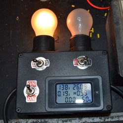
Power Up Vintage Electronics Less Unsafely With A Dim-Bulb Tester

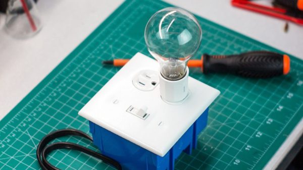
Plugging in something like an antique radio to see if it works is a good way to have a bad time, because some old components don’t age well. For vintage electronics, inspection and repair are steps one and two. When it comes time to cautiously apply power, it’s best to use what’s called a dim-bulb tester and most hackers can probably put one together from scrap.

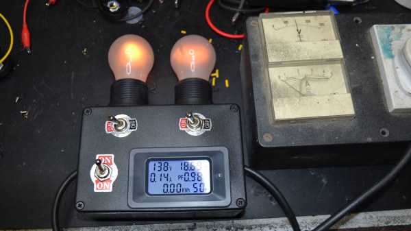
Being able to use one (or both) bulbs adds some flexibility, and the embedded power monitor is an inexpensive and handy addition.

These testers make it easier, and safer, to tell if there are any big problems with a device’s power supply. In its simplest form, a dim-bulb tester puts an incandescent lamp in series between a device — like an old radio — and the AC power from a wall socket. Thanks to this, if the device has a short circuit, the bulb will simply light up instead of causing any damage.

Ideally, one uses a bulb with a wattage rating that is roughly equal to the power consumption of the device being tested. If all is well, the bulb will glow very faintly and the device will work normally. A brightly glowing bulb would indicate excessive current draw. To allow some flexibility, [Doz]’s tester design allows using one or two 60 W incandescent bulbs in series, and even incorporates an inexpensive power monitor.

A dim-bulb tester isn’t an in-depth diagnostic tool but it is effective, simple, and allows for a safe startup even if there’s a serious problem like a short.  It helps protect valuable hardware from going up in smoke. In fact, the fundamental concept of limiting power to protect hardware in case of a fault has also been applied in the world of retrocomputing, where it helps protect otherwise irreplaceable hardware if something goes wrong.

A circuit board with a memory chip in a socket, and many memory chips in foam

Simple DRAM Tester Built With Spare Parts

Some of the most popular vintage computers are now more than forty years old, and their memory just ain’t how it used to be. Identifying bad memory chips can quickly become a chore, so [Jan Beta] spent some time putting together a cheap DRAM tester out of spare parts.

This little tester can be used with 4164 and 41256 DRAM memory chips. 4164 DRAM was used in several popular home computers throughout the 1970s and 1980s, including the Apple ][ series, Commodore 64, ZX Spectrum and many more. Likewise, the 41256 was used in the Commodore Amiga. These computers are incredibly popular in the vintage computing community, and its not uncommon to find bad memory in any of them.

With an Arduino at its core, this DRAM tester uses the most basic of electronic components, and any modest tinkerer should have pretty much everything in stock. The original project can be found here, including the Arduino code. Just pop the suspect chip into the ZIF socket, hit the reset switch, and wait for the LED – green is good, and red means it’s toast.

It’s a great sanity check for when you’re neck deep in suspect DRAM. A failed test is a sure sign that the chip is bad, however the tester does occasionally report a false pass. Not every issue can be identified with such a simple tester, however it’s great at weeding out the chips that are definitely dead.

If you’re not short on cash, then the Chip Tester Pro may be more to your liking, however it’s hard to beat the simplicity and thriftiness of building your own simple tester from spare parts. If you’re a little more adventurous, this in-circuit debugger could come in handy.

Continue reading “Simple DRAM Tester Built With Spare Parts”

DIY I2C Tester

[Dilshan] built a dedicated I2C tester which allows for I2C bus control over USB using simple commands such as init, read, write, etc. The Linux kernel has had I2C driver support for a couple of decades, but you’ll be hard pressed to find a computer or laptop with a I2C connector (excluding Bunnie Huang’s Novena hacker’s laptop, of course). This tester does require a Linux host, and his programs use libusb on the computer side and V-USB on the embedded side.

[Dilshan] put a lot of time into building this project, and it shows in the build quality and thorough documentation. With its single-sided PCB and all thru-hole construction, it makes a great beginner project for someone just getting into the hobby. At the heart of the tester is an ATmega16A in a 40-pin PDIP package (despite the Microchip overview page calling it a 44-pin chip), supported by a handful of resistors and transistors. Schematics are prepared in KiCad, code is compiled using gcc and avr-gcc, and he provides a label for the enclosure top. The only thing missing is information on the enclosure itself, but we suspect you can track that down with a little sleuthing (or asking [Dilshan] himself).

If you use I2C quite a lot, give this project a look. Easy to build, useful in the lab, and it looks nice as well. We have featured [Dilshan]’s work over the years, including this logic pattern generator and his two-transistor-on-a-breadboard superheterodyne receiver.

Universal Chip Analyzer: Test Old CPUs In Seconds

Collecting old CPUs and firing them up again is all the rage these days, but how do you know if they will work? For many of these ICs, which ceased production decades ago, sorting the good stuff from the defective and counterfeit is a minefield.

Testing old chips is a challenge in itself. Even if you can find the right motherboard, the slim chances of escaping the effect of time on the components (in particular, capacitor and EEPROM degradation) make a reliable test setup hard to come by.

Enter [Samuel], and the Universal Chip Analyzer (UCA). Using an FPGA to emulate the motherboard, it means the experience of testing an IC takes just a matter of seconds. Why an FPGA? Microcontrollers are simply too slow to get a full speed interface to the CPU, even one from the ’80s.

So, how does it actually test? Synthesized inside the FPGA is everything the CPU needs from the motherboard to make it tick, including ROM, RAM, bus controllers, clock generation and interrupt handling. Many testing frequencies are supported (which is helpful for spotting fakes), and if connected to a computer via USB, the UCA can check power consumption, and even benchmark the chip. We can’t begin to detail the amount of thought that’s gone into the design here, from auto-detecting data bus width to the sheer amount of models supported, but you can read more technical details here.

The Mojo v3 FPGA development board was chosen as the heart of the project, featuring an ATmega32U4 and Xilinx Spartan 6 FPGA. The wily among you will have already spotted a problem – the voltage levels used by early CPUs vary greatly (as high as 15V for an Intel 4004). [Samuel]’s ingenious solution to keep the cost down is a shield for each IC family – each with its own voltage converter.

Continue reading “Universal Chip Analyzer: Test Old CPUs In Seconds”

Continuity Tester Uses The ATtiny85’s Comparator

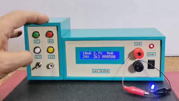
There’s an inside joke among cyclists – the number of bikes you need is “n+1”, where “n” is your current number of bikes. The same probably also applies to the number of tools and equipment a hacker needs on their workbench. Enough is never enough. Although [David Johnson-Davies] has a couple of multimeters lying around, he still felt the urge to build a stand-alone continuity tester and has posted details for a super-simple ATtiny85 based Continuity Tester on his blog. For a device this simple, he set himself some tall design goals. Using the ATtiny85 and a few SMD discretes, he built a handy tester that met all of his requirements and then some.

The ATtiny85’s Analog Comparator function is perfectly suited for such a tester. One input of the comparator is biased such that there is a 51 ohm resistor between the input and ground. The output of the comparator toggles when the resistance between the other input and ground is either higher or lower than 51 ohms. Enabling internal pullup resistors in the ATtiny85 not only takes care of proper biasing of the comparator pins, but also helps reduce current consumption when the ATtiny85 is put to sleep. The test current is limited to 100 μA, making the tester suitable for use in sensitive electronics. And enabling the sleep function after 60 seconds of inactivity reduces standby current to just about 1 μA, so there is no need for a power switch. [David] reckons the CR927 button cell ought to last pretty long.

For those interested in building this handy tester, [David] has shared the Eagle CAD files as well as the ATtiny85 code on his Github repository or you could just order out some boards from OSHpark.

MacGyvering Test Lead Clips

Okay fellow Make-Gyvers, what do you get when you cross a peripheral power cable jumper, a paperclip, springs, and some 3D-printed housings? DIY test lead clips.

Test clips are easily acquired, but where’s the fun in that? [notionSuday] started by removing the lead connectors from the jumper, soldering them to stripped lengths of paperclip, bent tabs off the connectors to act as stoppers, and slid springs over top. Four quick prints for the housings later, the paperclip assembly fit right inside, the tips bent and clipped to work as the makeshift clamp. Once slipped onto the ends of their multimeter probes, they worked like a charm.

Continue reading “MacGyvering Test Lead Clips”

A Dual-purpose Arduino Servo Tester

RC flying is one of those multi-disciplinary hobbies that really lets you expand your skill set. You don’t really need to know much to get started, but to get good you need to be part aeronautical engineer, part test pilot and part mechanic. But if you’re going to really go far you’ll also need to get good at electronics, which was part of the reason behind this Arduino servo tester.

[Peter Pokojny] decided to take the plunge into electronics to help him with the hobby, and he dove into the deep end. He built a servo tester and demonstrator based on an Arduino, and went the extra mile to give it a good UI and a bunch of functionality. The test program can cycle the servo under test through its full range of motion using any of a number of profiles — triangle, sine or square. The speed of the test cycle is selectable, and there’s even a mode to command the servo to a particular position manually. We’ll bet the build was quite a lesson for [Peter], and he ended up with a useful tool to boot.

Need to go even further back to basics than [Peter]? Then check out this primer on servos and this in-depth guide.

Continue reading “A Dual-purpose Arduino Servo Tester”