If you were given the task of designing a computer at a time when computers weren’t really even a thing, how would you start? How would you take a collection of vacuum tubes, passive components, and a precious few germanium diodes and engineer something to sell to customers looking for an “electronic brain”?
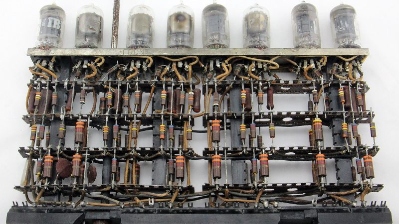
Where there’s a paycheck, there’s a way, and computer archeologist [Ken Shirriff] laid his hands on some old IBM hardware that tells us a lot about how engineers thought in the earliest days of the computer industry. The gear is a pluggable module from IBM, one of hundreds that once went into their Model 705 computer from the mid-1950s. The particular module [Ken] has is a 5-channel contact debouncer, or in Big Blue’s mid-century parlance, a “Contact-Operated Trigger.” It was used to debounce five of the many, many mechanical contacts in the machine, both buttons and relays, and used eight dual triode tubes to do it. Other modules with the exact same footprint formed the flip-flops, inverters, buffers and clocks needed to build a computer.
[Ken]’s analysis of the debouncer is a fascinating look at what was possible with the technology of the day, and the fact that it led to a standardized framework for generic modules that were actually hot-swappable with what essentially was a zero insertion force plug was quite a feat of engineering. And as a bonus, [Ken] and friends actually got the module up in running in the video after the break.
Jonesing for more retro-computer pluggable goodness? Check out this reproduction IBM flip-flop module from the 1940s.


i recently found a giant box that someone was throwing out full of resistors, capacitors, and diodes like the ones used in the module seen above.
Maybe the module has other functionality not discussed, but if the needed a debouncer, wouldn’t a simple RC circuit do the trick?
Debouncing requires hysteresis and hysteresis requires amplification.
Doesn’t require amplification, but it does require some kind of non-linearity, usually easily obtained through an amplifier.
8 triodes to debounce 5 relays! Makes sense!
Greenaum – 5 tubes are used to debounce 5 switches then 1/2 a tube as a output buffer. This would be the minimum circuitry needed for an active debouncer.
dahud – A RC circuit makes a poor debouncer. For starters you loose the sharp voltage rise and drop they demo in this video
3 Xs needed per relay, 2 Xs per triode.
Or as the article put it, complete with diagram mapping each part to each tube:
“The basic idea of this circuit is a resistor-capacitor filter (left) smooths out the input, removing any short glitches. This signal goes through two inverter circuits, creating a sharp output. Both inverters are part of the same 6211 tube and are wired as a Schmitt trigger. … The final output is buffered by a “cathode follower” circuit”
I’d expect there would be a whole chain of relay logic for the slower logic paths, and then a single debouncer at the end of it. Or if it is a synchronous design, it only needs debouncing for clock and asynchronous set/reset signals.
That would make sense. Because otherwise surely it’d be better to throw the 5 relays out, replace them with 5 triodes, and use the other 3 to make a radio or something. The computer would run hundreds of times faster too.
What are we going to call techno-archaeology ?
Massive props for:
1. Having the complete module
2. Figuring out what it is and what it’s from
3. Drawing a schematic of it
4. Applying power to it without destroying it
5. Actually getting it to work!
(and extra credit for using a filament transformer for its intended purpose)
That’s a big metal watch…
“Where there’s a paycheck, there’s a way” – words to live by
Interesting to read the comments that come from a today perspective it is worth noting that the IBM boys were starting from ground zero but without their brilliant work would we be where we are today