Remember a the time before oscilloscopes had a brain? It’s easy to forget as we’ve become accustomed to a class of simple solid state oscilloscope using a microcontroller as signal processor and a small LCD display to show the resulting waveforms. They are commonly available as inexpensive kits, and while their bandwidth is not huge they give a good account of themselves in low frequency applications. But of course, originally the signal processing was handled in a much simpler way.
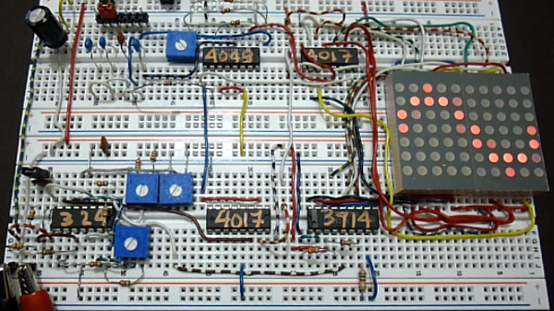
[SimpleTronic] reminds us that a small solid state oscilloscope does not need a microcontroller, with a ‘scope on a breadboard that displays waveforms on an LED matrix in a much more traditional manner. This is very much an analogue oscilloscope, in which the X deflection circuitry of the CRT is replaced by a decade counter stepping through the columns of LEDs on the display, and the Y deflection circuitry by some analogue signal conditioning followed by an LM3914 bar graph display chip driving the display rows. There are a few refinements such as a trigger circuit, but it remains a very understandable and surprisingly simple device.
It has a claimed bandwidth of 40 kHz defined by its sweep ranges rather than its analogue bandwidth, and an input voltage range from 50 mVpp to 50 Vpp. It’s hardly a useful instrument due to its low bandwidth, but its strength lies in novelty and in understanding a traditional oscilloscope rather than in its utility. You can see it in action in the video we’ve placed below the break.
‘Scopes of limited use appear from time to time on these pages. A favourite of ours is this soldering iron.


I have had pretty much this exact design in my mind for years now. I’m too much of a noob to have the chops to pull it off – but have definitely thought of using bar graph drivers and 4017 decade counter to whip up a pocket size audio scope.
“This is very much an analogue oscilloscope, in which the X deflection circuitry of the CRT is replaced by a decade counter stepping through the columns of LEDs on the display”
No, that is very much a digital oscilloscope. If your signal voltage is electrostatically deflecting an electron beam that excites a phosphor, or if your signal voltage deflected a galvo mirror that points a laser at a screen, then that would be an analog oscilloscope.
hmm… I wouldn’t call this a digital scope either. I guess it’s a hybrid. It takes analog measurements and displays in real time- no sampling.
I consider ‘digital scope’ to actually mean Digital Storage Oscilloscope. With that in mind, a digital scope may or may not deflect an electron beam for display.
The horizontal (timebase) is entirely digital. The vertical is a Sigma-Delta type A/D converter with a binary to decimal converter with parallel output (in the same package). The triggering is analog, but that’s not unusual in oscilloscopes, even when the trigger threshold is set digitally.
“No sampling”- It does sample, that’s how the vertical axis is created. It does not store the values though.
“No sampling” is not unusual for older mixed digital analog scopes either. Especially for mixed technology “Digital Sampling” scopes like the HP / Agilent 54500 – 54600 series which used a CRT, and could display the analog signal directly, but would also digitally sample and could store the waveform for latter measurement and display.
Yes this is very much a digital scope. Sampling or not is irrelevant. Both horizontal and vertical deflections are digital representations of the analog signal.
@Brian said: “The vertical is a Sigma-Delta type A/D converter with a binary to decimal converter with parallel output”
Did you WATCH the video? Have you read the datasheet of the LM3914? Do you always make shit up out of thin air?
“It does sample”
No. It *REALLY* does NOT. For as long as a particular column is on, the LEDs are updated CONTINUOUSLY. Since when does a single sample contain multiple values? It’s literally quantized analog, that reacts at audio rates.
It’s a stack of comparators that act like a flash ADC, It does not sample.
What do you think “Sample” means? It does sample, in that it assigns a digital value to an analog voltage level and displays it, but it does not store the value for latter display. So, it does not sample in the conventional sense, but instead immediately displays the measured value.
The stack of comparators act (effectively) as an ADC with decimal outputs.
“sample” in the relevant jargon means quantized in time. It is orthogonal to whether output values are quantized in value.
Hence “sample-and-hold” circuits, which are purely analog.
Everything is digital here. The triggering is a comparator, which is not unusual for any scope type. The horizontal is driven by a decade counter, and the vertical is driven by a stack of comparators, which act (effectively) as an ADC with its binary output converted to decimal.
Let’s settle on “discrete”, shall we?
The Y axis is literally ANALOG from beginning to end. That makes it an analog scope.
The IC that drives the Y axis, a LM3914, is literally a 3.3 bit flash ADC (it contains 10 comparators) with unary outputs.
The only difference between the LM3914 and something that is really unambiguously digital is that typical flash ADCs have a priority encoder integrated to convert the unary to binary; here we’d have to add an external IC like a 74LS147.
Like most flash ADCs, there is no sample clock.
A long long time ago in a country far far away from wherever… was a magazine called Elektuur, they had a design for an LED oscilloscope. I always wanted to build one but the lack of resolution combined with the huge amount of LED’s scared me for a long time… So eventually (after a few summer jobs and many savings of my allowance) I bought a “decent” but very old second hand 20MHz dual channel Philips oscilloscope. Which served me well for many years, but the LED design always remained in the back of my mind.
This project uses LED matrix modules which simplifies the build (by reducing component count and preventing polarity mistakes). Indeed from a practical point of view this is very close to worthless but from a teaching point of view this is a really great project/build for schools. Thanks for posting.
Yes! I built the Elektuur (Elektor) one when I was 15, this was 1996, and it actually worked but as you say resolution was very limited. 160 red LEDs were used. I threw it away at some point (still regret that…)
Sorry, but not so. This was a Forrest Mims article in Popular Electronics August 1979. Been repeated and rediscovered many times. Thirty seconds of google gives me these references and many more.
https://hackaday.io/project/19472-led-oscilloscope-mk-ii
http://blog.3b2.sk/igi/file.axd?file=2015%2F3%2FSolid+State+Oscilloscope.pdf
http://nicadiagram.blogspot.com/2013/03/100-leds-solid-state-oscilloscope.html
I was about to post that very observation, and took the time to read the comments to see if anyone beat me to it.
Ha, I read that book cover to cover many times. I recently saw a PDF of the book, and .. doh .. the passage of time changes everything. It actually made me aa little sad, like watching a concert tha tis basically a geriatric redux of a once mighty rock band.
Yes yes yes thank you. And I built this exact circuit on protoboard while I was in Junior high (not for school. As a hobby).
Still an excellent project for learning how to lay out chips and parts and hand route wires on perfboard.
Complex enough to be a challenge. Simple enough that most people will have some for of success if they just take their time over a few nights.
Here it is: https://americanradiohistory.com/Archive-Poptronics/70s/1979/Poptronics-1979-08.pdf That’s page 78 of the magazine or 72 of the pdf.
I think I’m destined to build one of these some day. I first saw the schematic somewhere else when I was a kid, probably a later edition of PE. I desperately wanted to build it then because I thought it would actually work as a useful tool. I didn’t know any better. I also couldn’t quite get the parts scrounged together so it never happened.
Much later, as an adult I came into posession of a large collection of old electronics magazines. I thought it would be interesting to read the one for the year and month that I was born. There it was again! So far that’s the oldest mention of this circuit that I have seen but it got around so much… I almost expect to find it as an application example in the original datasheet of whichever of those ICs came out last.
Yep I remember my dad gave me one of those Forrest Mims books and I made my first pcb just for that project!
Very similar to the design featured in Radio-Electronics in the mid 1980’s (I don’t have the reference handy, and it isn’t on the very incomplete Wikipedia page of projects). IIRC, that was a 10X10 LED matrix (individual LEDs at that time) with a 4017 and LM3914, but I don’t recall the triggering scheme.
Yup, I’ve seen that one too, here it is:
http://blog.3b2.sk/igi/file.axd?file=2015%2F3%2FSolid+State+Oscilloscope.pdf
No triggering in this one, as far as I can tell
Yes, I remember that too. ‘even made a PCB and just dug it out. It has an LM3914, a CD4011, and two CD4017’s. I made it in about 1991.
Picture: (no op-amp or 4049 though)
https://imgur.com/folb1FA
You’ve done most of the hard part!
If I had that lying around as one of my old projects I’d add a microphone and a small 2 or 3 transistor mic amp. Then I’d mount the whole thing in a shadow box with a hole drilled in the bottom, stuffed with a DC barrel jack. Then I’d mount it on the wall and power it with a wallwart that has a wire that color matches my wall.
Hmm… definitely a future project.
I seent one also, maybe Practical Electronics, it was more of a logic probe with a starburst segment character display, it wasn’t really really a scope but just indicated whether it was a squarish, triangle-ish or sine-ish wave that you were poking at.
“Remember a the time before oscilloscopes had a brain?”
Or a heart. ;-)
Fuck, so now I have to troubleshoot my circuit and my scope. :-p
Hum, most of use have. We used the bullet holder for .22 caliber bullets , it held 5 rows by 10cols, and we built it just like this, design was in popular electronics many many years ago
I imagine most of us have, several actually.
pop electronics had one, so had elektor.
Do an image search for “LED oscilloscope” and be amazed ;)
In the mid to late 70s, one of the columnists at “Popular Electronics” magazine had a real thing for making little scopes like this and printed lots of circuits that he and his readers designed.
Could’ve used a 555 like in the August 1979 Popular Electronics article.
forrest mims led oscilloscope. Pop electronics and Notebook series. Poor resolution.
Forrest Mims wrote about one in the August 1979 copy of Popular Electronics. I pulled out my copy and took a pic. https://i.imgur.com/80lr7pb.jpg
Yah I’m sure I built mine out of pop electronics back in the day.
Though it was early 1990s not 79 (I was 2 years old lol)
Me too. Went through many bags of LEDs from Poly-Paks to get enough good ones
Forrest Mims for President.
If this is a solid state scope, what are all the others then? I may only have been using scopes since the mid 90’s but I haven’t seen a scope yet that has more moving parts than the knobs.
I guess you have never used a 500-series Tek scope – vacuum tubes in all 6 directions…
No, I can’t say that I have. Although we do have an ancient (design looks like 1940’s) locally manufactured scope in the basement at work, I’ve never tried firing it up. I don’t even know what voltage/frequency it expects. Given the time period it might even be DC.
I like it!
I built one very much like this. It was coming up with 100 LEDs that was the killer, as I recall. I fumbled with the triggering circuit for a while, but without a ‘scope to see what was going on, it was difficult. I really wanted to make it 20×20 LEDs, but 400 LEDs are even more expensive, and surplus LEDs suffered from different brightness.
Then I bought an ancient 5MHz tube ‘scope and abandoned the LED ‘scope.
A very similar design was in a German electronics magazine, many years ago (i think it was elector). They used single LEDs instead of modules, though.
I have the part list for that thing stored as a shopping list on the webshop of a local electronics supplier for some years now, and each time i order something i muse that i should finally buy the stuff and build it. Then i opt against it “no, not now, to many other stuff”…