If you want to integrate a nice graphical interface with a microcontroller or single-board computer for a useful piece of custom equipment, how will you go about it? MyOpenLab is a platform that makes it easy to design virtual interfaces your electronic builds. If you want controls and readouts for Arduino, Raspberry Pi, Android, or anything with a serial port, this is worth a try.
MyOpenLab reminds me of LabView. Not so much modern LabView with all of its add-ons and extras, but LabView back when it did just a few things but did them really well. The open source MyOpenLab project has been around for a while. The website and documentation are not in English, which may have kept some people from giving it a try, but the software itself is available in German, English, and Spanish. I took the plunge and found the language barrier didn’t cause me trouble.
As an example of what you can do, image you want to build a custom bench tool. You build virtual device (they call it a “VirtualMachine”) that uses your computer as the control panel and readout, and your electronic project as the physical interface. In myOpenLab your device will consist of two parts: a diagram and a front panel. Some things only live on the diagram, like a timer or a connection to an Arduino. But some things live on both like switches, LEDs, graphs, and so on. You can connect all the little boxes together to build up applications. They can stand alone, but the power comes in being able to connect to an Arduino or Raspberry Pi (or a few other options) for I/O.
A Quick Project
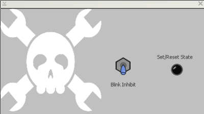 Before getting into the gritty detials, let’s look at a simple demo I cooked up to try things out. There are also plenty of substantial examples already in the VirtualMachines folder you can examine.
You can see the front panel here. The Jolly Wrencher is just a graphic added for decoration along the other items and labels that make the front panel look nice but don’t show up in the working diagram. The diagram is where you specify connections between your virtual front panel and actual hardware you want to control. You also have the power to add logic to existing hardware inputs.
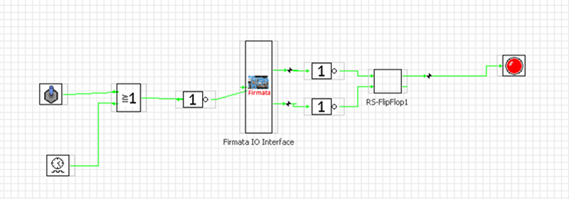
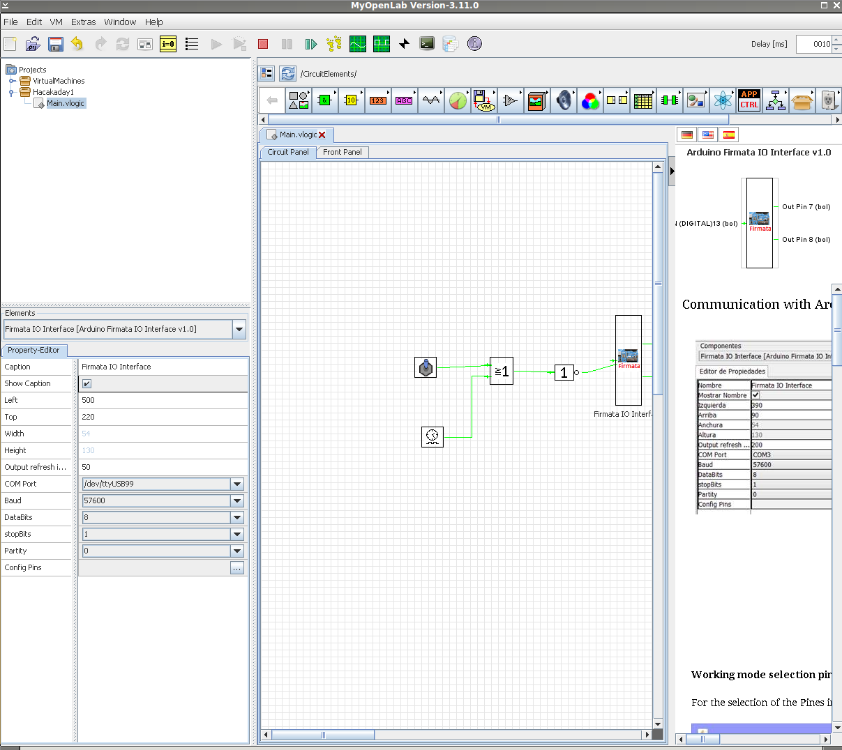
The Firmata block (Firmata is a protocol for communicating with microcontroller boards) is used to represent the hardware interface of your project and has a few interesting properties. First, you really need your board hooked up and working before you put the block down as it reads things even before you run your virtual machine. You can set the serial port to use and the refresh interval for inputs (apparently in milliseconds).
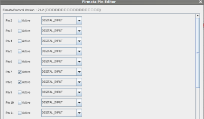
I wired two buttons connecting an Arduino’s pins 7 and 8 to ground, each with a 10K pull-up resistor. This biases the pin values so that MyOpenLab can read a 1 on those input pins when the buttons idle and a 0 when the buttons are pressed. I use this to illustrate the cool logic abilities of MyOpenLab. On the right side of the firmata block I invert the buttons since they are active low and then feed the result to an RS flip flop. A virtual LED on the front panel shows the state of the flip flop.
To the left of the firmata block, I have a slow timer and a virtual switch. This goes through an OR gate and an inverter to drive pin 13 of my Arduino (the LED built into the board). The net effect is the LED will blink unless you turn the virtual switch on the MyOpenLab front panel on. It is MyOpenLab that times the blinking.
You can also right-click on a wire and set a testpoint. During operation, you can open a window from the Window menu and display the test points easily. You can also open a little oscilloscope display that will show you all your digital or analog signals.
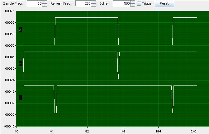
Pretty simple and while this is a silly example, you can see from the components you could put together a pretty significant system. There are quite a few examples in the VirtualMachines folder if you want to look at some meatier examples.
Now lets get into the details of working with MyOpenLab.
Working with the User Interface
The user interface is not bad at all. On a high-DPI monitor I found it is a bit small and there wasn’t a clear way to zoom it (but I’ll tell you how I fixed that later). Things work about how you’d expect. You pick components of the horizontal palette above the workspace then click on the workspace to place them. Note the palette changes if you are on the diagram (circuit panel) or the front panel.
Once in a while, you’ll see something that didn’t get localized for the English version of the software (the contadores de tiempo folder has timers in it). I also ran into a few components that insisted on throwing Java errors pretty much nonstop related to painting. They seemed to work, they just threw some Java exception. I did work out some Java fixes under Linux which I’ll detail later on.
Drawing interconnecting lines was a bit difficult. You have to start from the source, click, and then move to the destination and click again. The green lines were hard to see on my monitor and there was no way I could see to change the colors. You can only connect one output to one input. If you right click on a wire, though, you can add a node which will allow you to make another connection to that node. You can also pick the splitter component from the extras folder.
If you click on an object, there some help text that shows up on the right (often missing) and a property inspector on the left. Some of these require a little detective work on your part. For example, in the timer component, the high-level property sets the time in output is high and low-level sets the time the output is low. Both times appear to be in milliseconds.
Back End
What was interesting to me was the number of backends available as I/O devices. You can talk to an Arduino using Firmata but several others are also available. You can talk to a Raspberry Pi, Modbus, Processing, several commercial I/O interfaces, and the RS232 port. I wished there was a backend for Sigrok or USBTMC.
Then again, this is open source, so I guess I should add it instead of complaining. The project is hosted on SourceForge. Don’t get confused by the code you’ll get using the download button there (that’s an old version). If you look on the “code” tab you’ll find the subversion details to check out the most recent code:
svn checkout https://svn.code.sf.net/p/myopenlab3/code/ myopenlab3-code
Work Arounds
Getting things to work was a little challenging. Many Java programs don’t pick up my big screen correctly — I probably need to update my JVM. After I got tired of squinting, I ran Xephyr and passed it a fake DPI:
Xephyr -dpi 100 :3 -screen 1800x1200 -dpi 100  ; DISPLAY=:3 twm ; DISPLAY=:3 ./start_
linux &
Xephyr is like Xnest. It creates a virtual X Windows display in a window on your desktop. That made the mouse cursor a little funny which didn’t help with the wiring, but it was workable. Sure would be nice if the interface could zoom in and out, but as far as I could tell it doesn’t.
However, I had an even bigger problem. The program depends on the RXTX library to talk to the serial port. At first, it could not find my installation. I knew it should work because the Arduino IDE uses the same library and that was fine.
-Djava.library.path="/usr/lib/jni/"
But that wasn’t the end of the problem. The Arduino enumerates as /dev/ttyACM0 or perhaps some other number depending on what else is connected. The program would find ports that show up as /dev/ttyUSB* and /dev/ttyS* but didn’t want to show any ports with ACM in them. In a Kobayashi Maru maneuver, I issued the following command:
ln -s /dev/ttyACM0 /dev/ttyUSB99
Then MyOpenLab found /dev/ttyUSB99 and I was in business. I don’t like to lose.
More Resources
There’s a lot more to explore with this tool. There are dozens of components ranging from simple gates to PID controllers. However, this should get you started. If you speak Spanish, you are set. If you don’t, don’t forget that your browser probably has a translate button or you can use an online translator — you may have to hunt to translate the whole manual (or borrow my copy). Of course, the translations leave something to be desired. There is a forum that has a good bit of English. There’s also a YouTube channel, that has some English and was updated recently.
One thing to note about the YouTube videos. At least some of them have some English subtitles. For example, check out the introduction video below and turn on closed captioning in the YouTube viewer. Unfortunately, the translation stops when you get to the good stuff, but you can still follow what’s happening pretty well.




ahhh LabVIEW… everyone who has ever used it will agree when I ask “where’s the #$#$%#% zoom button!!!”
Because how wonderful and practical LabVIEW can be, I still cannot understand why they still haven’t added a simple zoom function in the block diagram editor. LabVIEW exists for more the 30 years… you would expect somebody from National Instruments would have taken this problem serious?
Other then that, 30 years for a piece of software is a great achievement. The main selling point to me is that they allow you to open old programs in new versions of the editor and the other way around if you save it correctly. This makes me happy when I make a piece of testsoftware that has to function AND be maintained for at least 15 years.
Regarding the project Myopenlab, a great project, if it is still available and maintained in 2028 I’ll sure give it a try.
“I still cannot understand why they still haven’t added a simple zoom function in the block diagram editor.”
That’s because one of the NI golden rules states that a “good .vi” (LabView program) should be contained in “one page”. As a LabView user I must admint that this is pure utopia….. who can resist to some spaghetti code ? :-)
no, id didn’t mean zoom out (making things smaller) I meant zoom in. Because the connections on some VI’s are simply so small you can hardly see them. No problem if you have a VI with just one in and one output, but when you have a VI with many wires, It’s nice to see what you are doing, because it’s easy to connect wires to the wrong input. Fortunately labVIEW shows you the name of the in or output when you hover your mouse over it. But come on… is it so much to ask to have a zoom function?!? If you search for a solution on the internet all that comes up is to use the microsoft windows magnifier…
You could say that I’m an old guy with bad eyes, but everyone who has worked with labview for a long period of time will confirm that this is a serious issue. This becomes more and more of a problem as the resolution of computer displays increases but screensize doesn’t. In other words, the pixels are getting smaller and smaller, therefore the lines on labview get thinner and thinner. Therefore working with VI on a laptop can be quit a challenge.
Regarding the fact that it is best to write a program that has everything on one page is certainly true… but far from realistic. It’s like stating that a good program only has one function. Nothing is more frustrating then to debug a program that has it’s functionality hidden underneath 5 layers of sub-VI’s, keeping them all open and keeping a clear view becomes difficult then. So In practice I keep my programs functions not more then 3 levels deep. Everything I do more then once in the same program deserves a sub-VI and if I make a function that can be useful in other programs I also create a sub-VI. Writing a program that fit’s onto your screen is getting easier then it was before, but only because of the fact that the screensize of computer displays are increasing.
One final thing, the best way to keep a program small (or tidy) is by the use of statemachines, it keeps your program organized, structured and understandable. But it is also less intimidating to look at (compared to a piece of spaghetti code). But the most important thing is that it is (when combined with an event handler) much more responsive then a simple program that does some sequential things and checks the buttons when going along. Event handlers combined with statemachines are also a good way to keep the processor load as low as possible while still having a responsive program. For those who worked with labVIEW know what I mean, a simple loop, checking buttons 100’s of times a second will keep your CPU at 100% load, bringing the rest of your computer to a standstill. Trying to solve this by adding a wait function will reduce responsiveness. While a simple event handler can keep the loop time large (reducing CPU load) but wil respond instantly when a button is pressed.
Sorry… I’ve got a little carried away.
National instruments, if you read this… please give us a proper zoom-function.
The biggest reason they haven’t added it is that it might promote [even] worse coding habits. There has been a “navigation window” for years that acts as a sort of zoom for the diagram but it is really only needed for horribly written code/diagrams. Still, I wouldn’t mind an actual zoom for both the front panel and diagram if you’re running at some ridiculous resolution.
And especially that everything they sell just works.. It’s plug and play, and if it doesn’t work they send someone to help you. But at the price you pay everything that is the least they can do
LabVIEW, spaghetti code that actually looks like spaghetti
Couple of months ago I put bunch of Labview CD’s in the garbage. Working with Labview gave me severe headache.
Labview nxg has zoom.. nxg is such a huge change that they are keeping old labview in development simultaneously.
labview nxg… huge change… Hmmm… is this a good thing? Can is use it in combination with my old programs? As backwards compatibillity (being able to service 10 year old programs for factory test-systems) is a bit of an issue.
(but having the zoom function can change everything)
Can you run it on a Raspberry Pi to work with a sensor attached to the gpio?
I’m going to be using a load cell to measure torque on a 50’s reel to reel player, so this is relevant to my interests. I’d been thinking of using Mathematica.
I can count on my reproductive organs the number of times I’ve successfully launched someone’s Java application on the first go around. I’m sure this is awesome, but I’m getting an exception trying this in OSX. A younger me would dig into this and beat my head against the desk until I figured it out, but at this point in my life, I’ve resigned myself to the fact that java apps might just not work for me.
Yea I got a bunch of errors too. I haven’t confirmed yet but I believe its do to MyOpenLab only being compatible with JDK 8
English?
Oh man, tell me that firmata can work with an esp32 with some simple code. I have an esp32 with a bunch of IO connected to a train set amd I just havent built an interface for it yet. This would be a pretty fun first cut.
Oh man, that’s brilliant. Should be a snap to put turnout toggles and block indicators on a nice looking track diagram, plus throttles and stuff.
You neglected to mention that the archive contains *12,000* files!!! XO
Open source community needs this platform, unfortunately it needs translation and documentation aid… like badly!
It’s not very useful if you need to learn new language to use it properly or to use sketchy automatic translation.
If you’re fluent in Spanish and English, please… go and help to translate this into English and try to get the project in general adjust towards English since it’s at this point the universal language of technology… weather you like it or not.
It took so much time for KiCAD to shed the burden of “i don’t think this is going to be a big thing so i program it in French…”
It’s a huge burden for getting more developers and users.
Have different UI languages? Of course… just… don’t turn away so much potential developers for having Spanish in the source code and documentation.
Ditto.
Otherwise it’s not even worth the headache of messing with, open or no opensource. For $50 I can get LabView Home edition from NI and have something that works.
LabView Home is Windows-only.
I just want something I can use to put together a decent looking UI for a remote app for an old Toshiba TLP-770 and TLP-771 projector. It just needs buttons, each of which throws a specific text command at the COM port of the user’s choice. The command codes are all in the user manual, just like they used to be for dot matrix printers.
Has anyone even got this to start under Windows10???
I have installed JRE/JDK 8 on windows 10 since nothing was working with JRE/JDK 10 – still nothing. I get flashes of a couple of boxes and a java process that I have to manually kill. Any suggestions on running this software under Windows 10? I have used the appropriate downloads from their site.
Getting to this late, but there’s a solution to the usb-serial enumeration problem, at least on linux.
Look at /dev/serial/by-id/ and you’ll find your arduino or other serial thing enumerated with its own serial number as part of the virtual file name. You can pass this to anything that opens a serial port – just like you’d use /dev/tty/ACM0- and it’ll work, but always get the same hardware, not whatever was plugged in first. I do this a lot and it’s a life-saver around here. Dunno if this problem ever got solved in windows.
Plugging in an uno to this machine results in a file named /dev/serial/b-id/usb-1a86_USB2.0-Serial-if00-port0 for example, and it’ll be that on any linux machine, always. This link maps to /dev/ttyUSB0 too – but that might change (like in windows) when things are plugged in and removed.
The only issues I’ve had are with some super cheap USBserial adapters in Chinese programmable power supplies that all had the same serial #.
Well, i think english speakers should learn more languages… I understand English, some French, lots of Spanish, a little of German and my language Portuguese.