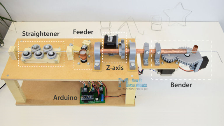
It’s been a while since we’ve shown a DIY wire bending machine, and [How To Mechatronics] has come up with an elegant design with easy construction through the use of 3D-printed parts which handle most of the inherent complexity. This one also has a Z-axis so that you can produce 3D wire shapes. And as with all wire bending machines, it’s fun to watch it in action, which you can do in the video below along with seeing the step-by-step construction.
One nice feature is that he’s included a limit switch for automatically positioning the Z-axis when you first turn it on. It also uses a single 12 volt supply for all the motors, and the Arduino that acts as the brains. The 5 volts for the one servo motor is converted from 12 using an LM7805 voltage regulator. He’s also done a nice job packaging the Arduino, stepper motor driver boards, and the discrete components all onto a single custom surface mount PCB.
The bender isn’t without some issues though, such as that there’s no automatic method for giving it bending instructions. You can write code for the steps into an Arduino sketch, which is really just a lot of copy and paste, and he’s also provided a manual mode. In manual mode, you give it simple commands from a serial terminal. However, it would be only one step more to get those same commands from a file, or perhaps even convert from G-code or some other format.
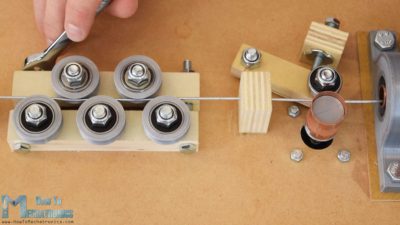
Another issue is that the wire straightener puts too much tension on the wire, preventing the feeder from being able to pull the wire along. One solution is to feed it pre-straightened wire, not too much to ask for since it’s really the bending we’re after. But fixing this problem outright could be as simple as changing two parts. For the feeder, the wire is pulled between copper pipe and a flat steel bearing, and we can’t help wondering whether perhaps replacing them with a knurled cylinder and a grooved one would work as the people at [PENSA] did with their DIWire which we wrote about back in 2012. Sadly, the blog entries we linked to no longer work but a search shows that their instructable is still up if you want to check out their feeder parts.
As for the applications, we can think of sculpting, fractal antennas, tracks for marble machines, and really anything which could use a wireframe for its structure. Ideas anyone?


This is wire bending. :) https://www.youtube.com/watch?v=SQIYZ-iKuG4 This DIY version needs a retractable bending peg.
Have you seen the video? It has retractable peg, that’s what servo is for.
It has a retractable peg. It also has a Z-Axit, whereas Gregg’s video looks decidedly 2D.
H2M’s is quite a lot slower, admittedly :-/
That would be handy for creating sections to be brazed/soldered/welded together to form a support frame for large-scale Pepakura projects.
Great effort well done, I’ve come across people who would buy these sorts of things np for pet art projects and to teach at schools too…
A bigger version for upgrading vehicle exhaust piping could be of interest, though how to scan for the requirement in-situ could be an interesting challenge:- Set cal/light points, scan with old pipe/muffler in place, remove old stuff, rescan, view model with differential and clearance area’s highlighted, amend etc…
Thanks for post :-)
Such thing exists commercially, though you’d usually cut out the bad part and use it as a template off vehicle.
I was referring mostly to sports mods where the whole set would be replaced with a so called ‘hi flow’ setup. Though are you staying there are places which do the 3D scanning as I mentioned, I’ve seen none across Australia – any in USA/Europe as after market sports/rally mods ?
im pretty sure that what he meant is that CNC tube benders exist as a commercial product. There are many different types of them as well depending on the final result you are looking for.
As for the custom 3d scanning, it is cost prohibitive as after-market exhausts are easily purchasable from many different manufacturers where they can take advantage of the economies of scale. floor pans and drive lines do not change until a major generational change in the car, so it makes more sense for a manufacturer to make exhausts en mass (like magnaflow for one example) rather than a shop to scan and bend exhausts individually.
There are also companies all over the world which will do custom 3d scanning of anything, not specifically for what you mentioned. How could any company make a profit off of 3d scanning such a limited market (you only need to scan a car once until the next body style change)
For completely custom exhausts it would be much less time and equipment investment in just buying pre bent pipes (for example: http://vibrantperformance.com/catalog/index.php?cPath=1022_1065) then cutting and tacking together the pieces in situ, like most exhaust shops already do.
PS this is my favorite of all the tube benders: https://www.youtube.com/watch?v=yigRgG_NIyU
Yup, used cnc bending for OEM & aftermarket exhausts. The pipes are defined as a series of centre points in 3d space & defining the radius where there is a change of direction. The tricky bit is clamping/ measuring them if you want to use a cmm. that is why a replacement custom exhaust maker wants to use the old one as a template.
Renishaw make some lovely manually-presented 3d probes which could generate a point cloud of the centreline or surface. Personally the I favour using a series of Vee-block measurements to generate a point cloud of the centreline. I imagine the advent of 9D MEMS devices for inclination and movement should almost make centreline acquisition a relatively cheap activity ( think 2 vee rollers on a carriage which you wheel along the existing pipe route).
Super project! Besides the fact that it reminds me of one of my favorite youtube videos ( https://www.youtube.com/watch?v=yigRgG_NIyU ) I think that this could be very useful for building Arthur-Ganson-style wire gears and mechanisms.
Here’s how Arthur Ganson makes his gears: https://www.youtube.com/watch?v=f0UNz-ayzrE and here’s an example of what he makes with the wire gears: https://www.youtube.com/watch?v=17IwzY8V5QA
Re: favorite video. Whoah! Crazy tube-bending machine.
https://www.youtube.com/watch?v=UTDXeORFX1k
:o)
Now THAT’s a Bender!
Have a look at wire feeders for MIG welders for ideas on how to make the feeder work well.
Are these related to the ones that run a DC current through then at the last wire feed to help straighten by annealing with the spinning wire brush to increase surface conductivity – or was that a dream as a contrived way to use weird wire spools some 30 years old ;-)
I’ve never seen spinning brushes in y years repairing welders, but the rollers are used to pass the welding current to the wire.
Often two wheels are used to increase traction, V-groove wheel against a plain bearing is used for solid wire, knurled wheel is used for flux core so it can still grip with less pressure to prevent crushing of the wire. U-groove on both sides is used for aluminium wire to prevent deforming the soft wire also.
Just a small detail but they don’t pass any current at the feed wheels. That’s done at the copper tip in in the MIG handle. Otherwise the whole wire would light up like an incandescent filament in the tube.
Ah yep, late night posting is my excuse…..
The weld current is passed from the welder to the feeder assembly which has the Euro plug/gun plug etc. attached.
This effectively energizes the wire, the feed tube (if metallic) and the cable running down to the gun.
As you mentioned, the weld current is carried by the wire alone only as it exits the nozzle.
Idea for you: Rather than the end-stop switch (or possibly IN ADDITION TO the end-stop switch) if you’re allowed to assume the wire is conductive, you could use electrical contact between the bending pin and ground (ground the feeder / straightener) to get your 0-degree point DEAD ON the edge of the wire. You could measure start-point of the wire (advance feeder until contact with pin), then explore a bit to find L+R sides of the wire, to determine width of the wire and best place to start bending L or R.
That thing is awesome!
even if you dont need a wire bender watching the video for his build techniques is worth it.
What would be really cool would to take text, say like a name, and turn it into gcode for the bender to make. It could be a 3d bend as well, perhaps. Hmmm….
Okay, now do all this PLUS FIRE and use glass tube instead of the wire, fill the result with neon…
Very cool build! I like the way he mixes wood and 3D printed parts.
Can this be used to make torsion springs? It doesn’t look like it, but I’ve never them before so who knows.
Nicely done. Since posted it in 2012, only a few people completed the project. Congrats!
Hello All,
Does this machine have 3D modeling ?
Can you share this with me ?
If you’re looking for the STL files for the 3D printed parts, there’s a link to them on his instructions page https://howtomechatronics.com/projects/arduino-3d-wire-bending-machine/ Scroll down to the heading “DIY 3D Wire Bending Machine 3D Model”.
Hello Dejan,
That coding uses for specific models (like star,cube) as I understand.
I would like to do complex models (like spline,spring ec.. )
Is possible that to do my draft which is created in Solidworks with arduino codes ?
For example, CURA is program which is using by 3d printer. I give STL model in CURA program, it prepares appropriate codes for 3d printer.
Is there such a program for wire bending ?
Friend, I built a machine like this and I also need this answer. Do you have any information?