
The Game Genie is a classic of the early 90s video game scene. It’s how you would have beaten the Ninja Turtles game, and it’s why the connector in your NES doesn’t work as it should. They never made a Game Genie for the Atari 2600, though, because by the time the Game Genie was released, the Atari was languishing on the bottom shelves of Toys R Us. Now though, we have FPGAs and development tools. We can build our own. That’s exactly what [Andy] did, and his Game Genie for the 2600 works as well as any commercial product you’d find for this beleaguered console.
To understand how to build a Game Genie for an Atari, you first have to understand how a Game Genie works. The hacks for a Game Genie work by replacing a single byte in the ROM of a game. If your lives are stored at memory location 0xDEAD for example, you would just change that byte from 3 (the default) to 255 (because that’s infinite, or something). Combine this with 6-letter and 8-letter codes that denote which byte to change and what to change it to, and you have a Game Genie.
 This build began by setting up a DE0 Nano FPGA development board to connect to an Atari 2600 cartridge. Yes, there are voltage level differences, but this can be handled with a few pin assignments. Then, it’s just a matter of writing Verilog to pass all the data from one set of address and data pins to another set of address and data pins. The FPGA becomes a man-in-the-middle attack, if you will.
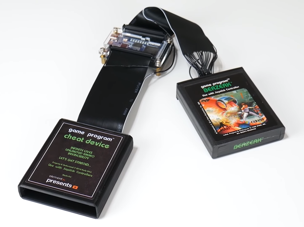
With the FPGA serving as a pass-through for the connections on the cartridge, it’s a simple matter to hard-code cheats into the device. For the example, [Andy] found the code for a game, figured out where the color of the fireballs were defined as red, and changed the color to blue. It worked, and all was right with the world. The work was then continued to create a user interface to enter three cheat codes, and finally wrapped up in a 3D printed enclosure. Sure, the Atari Game Genie works with ribbon cables, but it wouldn’t be that much more work to create a similar project with Lock-On™ technology. You can check out the entire build video below, or get the info over on Element14


Why doesn’t the connector in a NES work as it should?
Could be a comment on the fact that the NES used this fancy “push down to lock” mechanism in combination with card-edge. Which means the contacts of the carts could get dirty and while with a normal card edge, you would kinda clean them by pushing them into their slot. With the NES you didn’t have this sliding the connectors bit, and thus it would have contact issues quite easy.
The “push to lock” was most likely designed to prevent wear, but in the end, it worked against the system instead of for it.
I believe the design of the NES was driven more by marketing than by anything else. Specifically the desire to make the product feel more like a VCR than a games machine.
Yup, the NES was released to the US market right after the big video game crash, and no retailers wanted to be involved with or sell video game systems after the losses and flood of unsold inventories they just had to deal with.
That’s why NES = nintendo *entertainment system*, not game system. It was spun to be in addition to other living room entertainment like TV, and as you said the design was changed to more look like the front loading VCRs at the time.
It was also labeled as a “control deck” instead of a “game console”, using “software cartridges”
The top loading Famacon didn’t have these connector issues.
A related fun fact is that this was the only reason for ROB the robot to exist, not to be sold so much as convincing retailers the NES was a toy instead of a game system. ROBs primary value was getting the NES on the shelves, any of them actually sold was just icing on the cake.
Nintendo, in all their lack of wisdom, changed how the cartridges were sized, and stupidly left the circuit boards the same size, but I won’t get into that part. You know the big rectangular NES cartridges, but in Japan, the cartridges were like half that height, they were small rectangles. The NES in japan was like later revisions released in the US, where you can just pop the cartridge into the top. But front loader NES consoles had specific sizes in mind. And then comes the GAME GENIE. You plug the connector on your cartridge, not to the slot inside the NES, but into the game genie, and then insert the game genie into the console. But this meant the cart was now awkwardly sticking out and you couldn’t close the hatch. Google it if you don’t believe me.
Cuz the 72 pin connector inside the original NES was a turd. It would have stopped working without the use of the Game Genie but the Game Genie with a game cartridges connected was too long to slide in and press down like a regular game. So, the Genie and cart had to be pushed in at an angle bending pins and making them loose.
Note, this was a non-issue on the NES top loader.
Technically there was an issue with top loader. Game Genie didn’t fit the top loader well because of thicker board and the top loader wasn’t designed with ZIP connector like front loader. The lucky few who called Galoob to complain got a top loader version of Game Genie which is now worth a lot. The top loader version didn’t work in front loading console either.
Action Replay had it right, the board goes in with a connector on top rather than on end, so the cheat cart can be pushed down to lock the front loader correctly, and you can then insert a game to the connector on top of Action Replay. AR also worked with top loader because it used same PCB size as NES cart. Unfortunately AR is rare as hen’s teeth and some may need new battery + reflashing to get it working.
The funny part is that it’s of significantly higher complexity than the rest of the console. A simple MCU could do the job because normal carts maxed out at 4KB and with bank switching could have 32KB. It’s no stretch to think a slow poke AVR chip could manage this feat.
Except that you need to act like a memory bus, which requires some pretty quick response times. You would only have a few cycles in an AVR, at best.
Would probably need some extra hardware: a 12 bit (2*8 bit) binary comparator which disables the chip select for the ROM at a given address and enables OE\ for a single 8 bit register presenting the new value for this.
The register could even be a shift register where the µC preloads the new value. The comparator reference value could also be stored in a shift register or be presented on µC GPIOs.
There is no pass through necessary.
You could even do it without a µC: binary comparators, a multiplexer for OE\ between original ROM and the new register and a bunch of switches for adresses and data. In that case the register could even be substituted with a tristate buffer between the data switches and the memory bus.
Just read the ROM into a static ram chip and modify the relevant values. Then have a bus latch to control access between the 2600 and microcontroller. There is a product called “The Romulator” which does this already, it’s quite neat and well proven. It’s used for tuning car ECUs and other applications where you need to do ICE of a ROM chip.
“You could even do it without a µC: binary comparators, a multiplexer for OE\ between original ROM and the new register and a bunch of switches for adresses and data. In that case the register could even be substituted with a tristate buffer between the data switches and the memory bus.”
Except Atari 2600 didn’t have a /OE pin. They had only 8 data, 11 address, 2 ground, and 1 VCC line on the connector. You would need to monitor the address and data to check for write attempt to handle bankswitching. And pass the data through in a read mode, modified as needed such as unlimited lives, etc.
2600 was a difficult beast to work with. Other challenge: no video RAM means the game code has to continuously update the screen in real time while handling controller data, switch board data, and sending data to TIA for the screen. Using paddle controller eats up more of CPU cycles than joystick as it’d have to compute the paddle position at regular intervals.
AVR could theoretically be used to modify ROM data like Game Genie but it may not be fast enough to avoid breaking the video data, missing the important write for bankswitching, etc. It may be easier to modify the ROM on a PC, copy the modified ROM to Harmony cart SD or other flash cart and run that on 2600.
Correction: 13 address pins but that is all that you can access in a 2600 cart slot. No /OE
An AVR is guaranteeably too slow to act as a ROM emulator. There’s a modern ROM emulator for the 2600: it’s called the Harmony Cart and it uses a 70MHz ARM.
Yes, you can recapitulate the circuitry inside the original Game Genie in discretes. Doesn’t really count as “using a microcontroller” at that point, the micro is just serving as a glorified latch.
The atari 2600 only had 128 bytes of memory I remember some time ago taking a look at memory content of Frostbite with stella it was quite easy to directly search for the memory address of remaining lives.
“If your lives are stored at memory location 0xDEAD for example, you would just change that byte from 3 (the default) to 255 (because that’s infinite, or something). ”
Address Range
Function
$0000 – $007F
TIA registers
$0080 – $00FF
RAM
$0200 – $02FF
RIOT registers
$1000 – $1FFF
ROM
According to this site:
http://www.randomterrain.com/atari-2600-memories-tutorial-andrew-davie-05.html#memory_mapping
So 0xDEAD wouldn’t be a valid address.
The joke..
Your head…
You can’t poke at the console RAM via the cart connector, though… this device is basically an in-line ROM editor. Though you could probably replace a couple NOP with LDA #255; STA $01; and set your lives to 255 each frame.