FPGA Hack Becomes An Atari Game Genie

The Game Genie is a classic of the early 90s video game scene. It’s how you would have beaten the Ninja Turtles game, and it’s why the connector in your NES doesn’t work as it should. They never made a Game Genie for the Atari 2600, though, because by the time the Game Genie was released, the Atari was languishing on the bottom shelves of Toys R Us. Now though, we have FPGAs and development tools. We can build our own. That’s exactly what [Andy] did, and his Game Genie for the 2600 works as well as any commercial product you’d find for this beleaguered console.

To understand how to build a Game Genie for an Atari, you first have to understand how a Game Genie works. The hacks for a Game Genie work by replacing a single byte in the ROM of a game. If your lives are stored at memory location 0xDEAD for example, you would just change that byte from 3 (the default) to 255 (because that’s infinite, or something). Combine this with 6-letter and 8-letter codes that denote which byte to change and what to change it to, and you have a Game Genie.

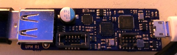
This build began by setting up a DE0 Nano FPGA development board to connect to an Atari 2600 cartridge. Yes, there are voltage level differences, but this can be handled with a few pin assignments. Then, it’s just a matter of writing Verilog to pass all the data from one set of address and data pins to another set of address and data pins. The FPGA becomes a man-in-the-middle attack, if you will.

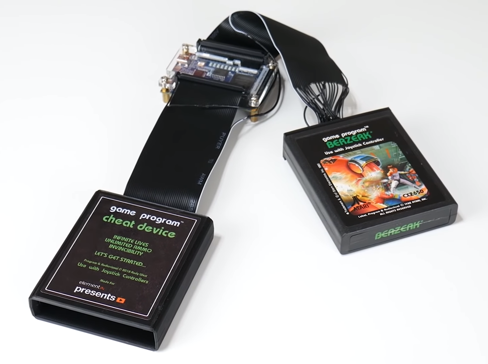
With the FPGA serving as a pass-through for the connections on the cartridge, it’s a simple matter to hard-code cheats into the device. For the example, [Andy] found the code for a game, figured out where the color of the fireballs were defined as red, and changed the color to blue. It worked, and all was right with the world. The work was then continued to create a user interface to enter three cheat codes, and finally wrapped up in a 3D printed enclosure. Sure, the Atari Game Genie works with ribbon cables, but it wouldn’t be that much more work to create a similar project with Lock-On™ technology. You can check out the entire build video below, or get the info over on Element14

Continue reading “FPGA Hack Becomes An Atari Game Genie”

Improving Depth Of Field With Only 5 Phones

The hottest new trend in photography is manipulating Depth of Field, or DOF. It’s how you get those wonderful portraits with the subject in focus and the background ever so artfully blurred out. In years past, it was achieved with intelligent use of lenses and settings on an SLR film camera, but now, it’s all in the software.

The franken-camera rig, consisting of five Pixel 3 smartphones. The cameras are synchronised over WiFi.

For the Pixel 2 smartphone, Google had used some tricky phase-detection autofocus (PDAF) tricks to compute depth data in images, and used this to decide which parts of images to blur. Distant areas would be blurred more, while the subject in the foreground would be left sharp.

This was good, but for the Pixel 3, further development was in order. A 3D-printed phone case was developed to hold five phones in one giant brick. The idea was to take five photos of the same scene at the same time, from slightly different perspectives. This was then used to generate depth data which was fed into a neural network. This neural network was trained on how the individual photos relate to the real-world depth of the scene.

With a trained neural network, this could then be used to generate more realistic depth data from photos taken with a single camera. Now, machine learning is being used to help your phone decide which parts of an image to blur to make your beautiful subjects pop out from the background.

Comparison images show significant improvement of the “learned” depth data versus just the stereo-PDAF generated depth data. It’s yet another shot fired in the smartphone camera arms race, that shows no signs of abating. We just wonder when the Geiger counter mods are going to ship from factory.

[via AndroidPolice]

MakerBot Moves Away From Makers With New Printer

If you’ve been following the desktop 3D printing market for the last couple years, you’re probably aware of the major players right now. Chinese companies like Creality are dominating the entry level market with machines that are priced low enough to border on impulse buys, Prusa Research is iterating on their i3 design and bringing many exciting new features to the mid-range price point, and Ultimaker remains a solid choice for a high-end workhorse if you’ve got the cash. But one name that is conspicuously absent from a “Who’s Who” of 3D printing manufacturers is MakerBot; despite effectively creating the desktop 3D printing market, today they’ve largely slipped into obscurity.

So when a banner popped up on Thingiverse (MakerBot’s 3D print repository) advertising the imminent announcement of a new printer, there was a general feeling of surprise in the community. It had been assumed for some time that MakerBot was being maintained as a zombie company after being bought by industrial 3D printer manufacturer Stratasys in 2013; essentially using the name as a cheap way to maintain a foothold in the consumer 3D printer market. The idea that they would actually release a new consumer 3D printer in a market that’s already saturated with well-known, agile companies seemed difficult to believe.

But now that MakerBot has officially taken the wraps off a printer model they call Method, it all makes sense. Put simply, this isn’t a printer for us. With Method, MakerBot has officially stepped away from the maker community from which it got its name. While it could be argued that their later model Replicator printers were already edging out of the consumer market based on price alone, the Method makes the transition clear not only from its eye watering $6,500 USD price tag, but with its feature set and design.

That said, it’s still an interesting piece of equipment worth taking a closer look at. It borrows concepts from a number of other companies and printers while introducing a few legitimately compelling features of its own. While the Method might not be on any Hackaday reader’s holiday wish list, we can’t help but be intrigued about the machine’s future.

Continue reading “MakerBot Moves Away From Makers With New Printer”

Open Hardware Board For Robust USB Power Monitoring

We’ve all seen the little USB power meters that have become popular since nearly every portable device has adopted some variation of USB for charging. Placed between the power source and the device under test, they allow you to see voltage and current in real time. Perfect for determining how long you’ll be able to run a USB powered device on batteries, or finding out if a USB power supply has enough current to do the business.

[Jonas Persson] liked the idea of these cheap little gadgets, but wanted something a bit more scientific. His design, which he refers to as UPM, is essentially a “smart” version of those ubiquitous USB gadgets. Instead of just showing the data on a little LCD screen, it can now be viewed on the computer and analyzed. His little gadget even allows you to cut power to the device under test, potentially allowing for automated testing of things such as inrush current.

Essentially the UPM works in much the same way as the simple USB meters: one side of the device goes towards the upstream power source, and the device under test plugs into the other side. Between the two devices is a 16 bit ADC and differential amplifier which measures the voltage and current. There’s a header on the board which connects to the ADC if you wanted to connect the UPM to an external microcontroller or other data logging device.

But most likely you would be using the internal microcontroller to analyze the output of the ADC over I2C, which [Jonas] very cleverly connected to the upstream port with an integrated USB hub. One side of the hub goes off to the device being tested, and the other to the microcontroller. So the host device will see both the UPM’s integrated microcontroller and the target device at the same time. From there, you can use the ncurses user interface to monitor and control the device in real-time.

While the hardware looks more or less finished, [Jonas] has some more plans for the software side of UPM, including support for remote control and monitoring over TCP/IP as well as robust logging capabilities. This is definitely a very interesting project, and we’re excited to see it develop further.

In the past we’ve seen homebrew USB power meter builds, and even commercial offerings which boasted computer-based logging and analysis, so it was only a matter of time before somebody combined them into one.

Modified F Clamp Is Wheely Good

Sometimes, a job is heavy, messy, or unwieldy, and having an extra pair of hands to help out makes the job more than twice as easy. However, help isn’t always easy to find. Faced with this problem, [create] came up with an ingenious solution to help move long and heavy objects without outside assistance.

Simple, and effective.

The build starts with a regular F-clamp  – a familiar tool to the home woodworker. The clamp is old and worn, making it the perfect candidate for some experimentation. First off, the handle is given a good sanding to avoid the likelihood of painful splinters. Then, the top bar is drilled and tapped, and some threaded rod fitted to act as an axle. A polyurethane wheel from a children’s scooter is then fitted, and held in place with a dome nut.

The final product is a wheel that can be clamped to just about anything, making it easier to move. [create] demonstrates using the wheelclamp to move a long piece of lumber, but we fully expect to see these on the shelf of Home Depot in 12 months for moving furniture around the house. With a few modifications to avoid marring furniture, these clamps could be a removalist’s dream.

While you’re busy hacking your tools, check out these useful bar clamps, too. Video after the break.

Continue reading “Modified F Clamp Is Wheely Good”

Julius Lilienfeld And The First Transistor

Here’s a fun exercise: take a list of the 20th century’s inventions and innovations in electronics, communications, and computing. Make sure you include everything, especially the stuff we take for granted. Now, cross off everything that can’t trace its roots back to the AT&T Corporation’s research arm, the Bell Laboratories. We’d wager heavily that the list would still contain almost everything that built the electronics age: microwave communications, data networks, cellular telephone, solar cells, Unix, and, of course, the transistor.

But is that last one really true? We all know the story of Bardeen, Brattain, and Shockley, the brilliant team laboring through a blizzard in 1947 to breathe life into a scrap of germanium and wires, finally unleashing the transistor upon the world for Christmas, a gift to usher us into the age of solid state electronics. It’s not so simple, though. The quest for a replacement for the vacuum tube for switching and amplification goes back to the lab of  Julius Lilienfeld, the man who conceived the first field-effect transistor in the mid-1920s.

Continue reading “Julius Lilienfeld And The First Transistor”

Off Road Vehicle Has Six Wheels And Fluid Power

What has six wheels and runs on water? Azaris — a new off-road vehicle prototype from Ferox. Azaris has a rocker suspension modeled after the one on the Mars rover. The problem is, linking four drive wheels on a rocker suspension would be a nightmare. The usual solution? Motors directly in the wheels. But Ferrox has a different approach.

The vehicle has a conventional BMW motorcycle engine but instead of driving a wheel, it drives a pump. The pump moves fluid to the wheels where something similar to a water wheel around the diameter of the wheel causes rotation. The fluid is mostly water and the pressure is lower than a conventional hydraulic system. Auto Times has a video of some stills of the prototype and you can see it below. We haven’t actually seen it in motion, unfortunately.

Continue reading “Off Road Vehicle Has Six Wheels And Fluid Power”