If there’s one thing that will bring down the yield of your PCB assembly, it’s your solder paste. Put too much on, and you’ll get bridged leads. If you don’t put enough on, that pad might not make good contact. [ScalarElectric] has an amazing trick that’s sure to astonish and astound. Just use wedges and you’ll get better yield with fine-pitched components.
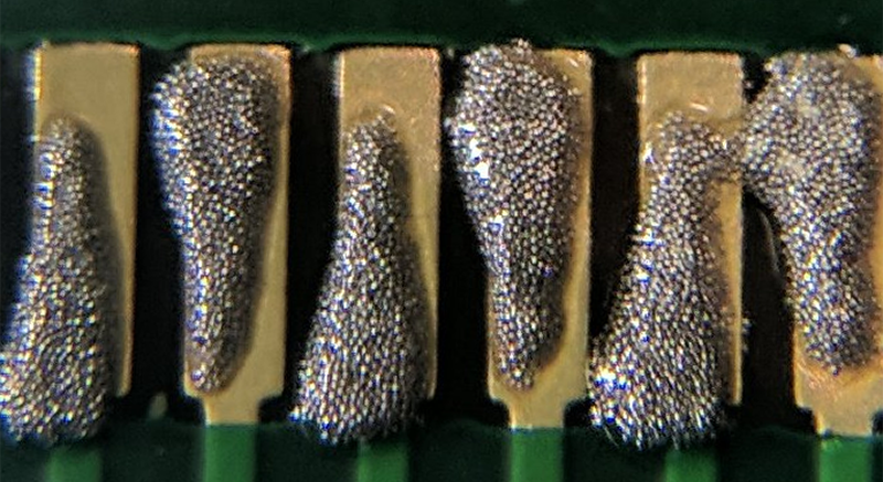
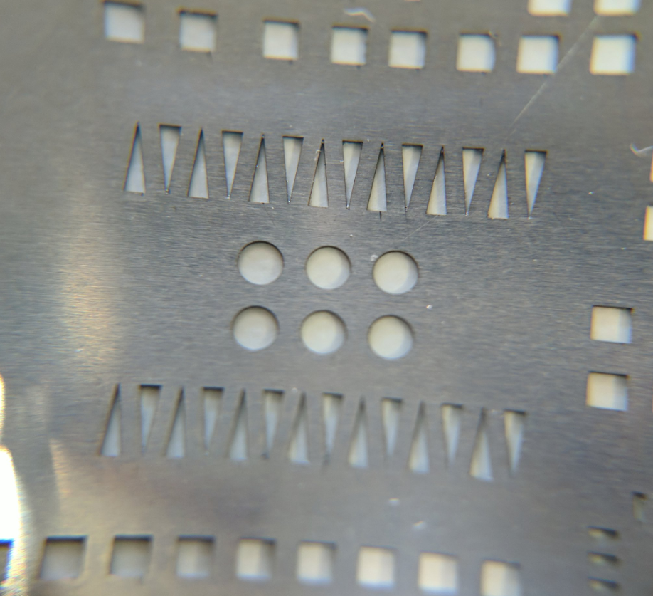
The trick here is to define the cream/solder paste layer of each package as a wedge on each pad instead of the usual rectangle. This gives a few benefits, the largest being the increased gap between paste shapes. You’re also getting a reduction in the total amount of paste applied, and a subsequent improvement in yield. (Reportedly, we’d love to see some data on this.)
PCB design tools usually have a way to alter the size of the cream/solder paste layer of a design, and indeed one option is to simply shrink the size of the paste layer elements. The trick to the wedges is increasing the total distance between solderpaste blobs while keeping the total amount of solderpaste high. This technique can be used down to 0.5mm pitch parts, and everything works like a charm.
While this is a little outside of our wheelhouse here at Hackaday — it is, after all, a novel use of existing tools that is mostly applicable to electronic design and production. [Ed Note: Sarcasm.] You can check out a few pics of this technique in the slideshow below. If you test this technique out, be sure to let us know how it went!


Wow, great idea.
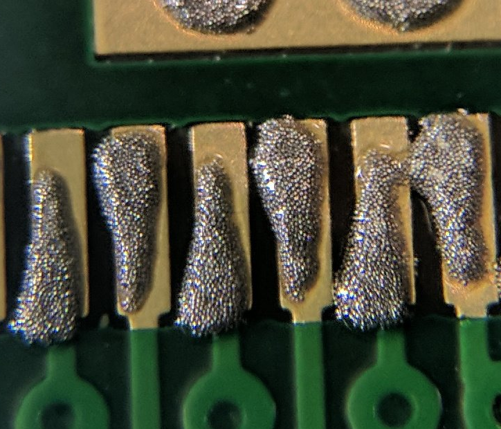
Lol, is that a solder bridge on the last one?
Yes. Just about.
It is at the paste stage, but once reflowed, surface tension will pull that apart. Hopefully.
What I’m not clear about, is how a wedge is superior to just using a narrower rectangular shape.
o/~surface tension
will pull that apaaart o/~ again
I feel like it’s superior to a narrower rectangle in that it looks like it allows more solder paste but still having a decent gap. The bulge alternates between pins but allows more solder to flow onto the component.
I think allows for more volume of paste while keeping a greater minimum distance between the pads
Please help me to understand this. If there’s a certain amount of area you want to cover with paste, and a certain amount of separation you want between the globs of paste, the BEST way to do this should be with rectangles. I don’t have enough brain capacity available right now to go into this, but it seems like slanting the gaps makes the distance between the globs SMALLER. I think it has something to do with the sides of a parallelogram being closer together, the more you tilt the parallelogram.
Hopefully yes. But wasn’t this actually supposed to fix that with a wider area between paste patches…
… but perhaps not once it’s heated. Likely shrinks back.
Bad idea as the very sharp corner is more likely to get stuck on the stencil. You would have to round the corners making this only applicable to larger pads where rectangular shapes already work well. Choosing different finish on your stencil and different solder paste will fix any issues even down to 0.5mm pitch.
Fully agree with you. These sharp corners give absolutely no consistent result in amount of paste applied, There will always be some paste stuck in that wedge. I design all my pads (or at least the paste masks) with rounded corners for easyer paste release.
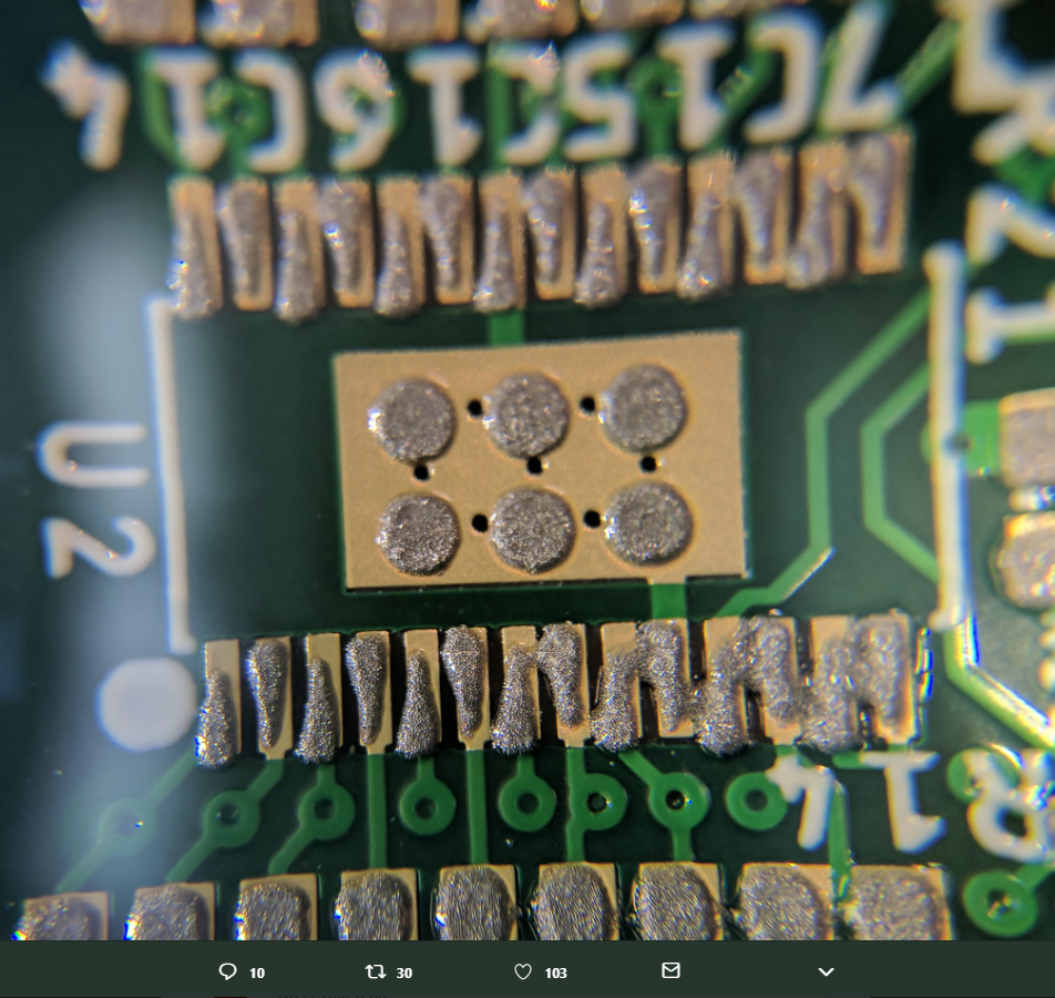
The biggest problem with this board shown here in the article is that he is missing a solder mask strip in between the pads (you can see it very well on one close up picture). Thats where the issues with solder bridges between pads in his design come from.
From presonal experience with a lot of 0402 size passives and QFN packages with 0.4mm pitch i really don’t see any need for a wedge paste mask on a rectangular pad. And yes, i do prototypes with manual stencil placement and paste application too.
Yup, and solder paste touching is an imagined problem. So long as the quantity is right, you sent get bridging. When using a dispenser, you can just put a bead straight across all the pins.
As you mentioned above, I also put a little bit of a curve into the corners. I also shrink the windows, but only in the direction that makes them more square. It gives the most consistent release.
hmmm… at first I thought this would have been an interesting idea, then I noticed the images of solderpaste triangles still touching each other. To me this doesn’t feel like a solution to a problem but simple a way to cover up a systematical screwup. Stencils have a certain thickness for a reason, if you apply too much paste, then you’ve ordered a stencil that’s to thick or you are not applying it in the proper way, use the wrong paste, blabla etcetera.
At work we frequently use 0.4mm pitch and a 120um stencil, paste is applied manually, so no automated squeegee or any of that fancy stuff. It is a process that requires some skill, but if you feel it’s necessary to order a stencil, then at least take the time to learn how to use it. And if not then simply remove the part from the stencil and drag-solder the component manually. Alignment of the stencil related to the PCB is an important thing to keep in mind, looking at the photos there is room for improvement.
‘simple’ —> ‘simply’ —> ‘simplify’ ;)
Well said. I have always found shrinking the paste aperture size will remedy any solder bridging problems with fresh paste. I have also found diluting the solder paste using paste flux gives the best result with little chance of bridging, as long as the proportion of paste flux is kept small.
You’re supposed to place the paste on the pads, not anywhere near them.
Negative! When you place the solder paste “anywhere near a pad” it will reflow onto the pad and solder just fine. If you can, it pays a bit to prevent it, but “anywhere near” will work in practice. So an 0805 resistor is about 1×2 mm. Move it sideways by 0.5mm and forget you needed a new stencil and half the paste goes beside the pad. Place the resistor on the pads (not on the paste) and… perfect reflow!
yeah, that works for 0805. When you’re doing 0.5mm TQFP, proper alignment and using the right amount of paste becomes much more critical.
I concur.
Use better solder paste. I was using some MGN lead free trhing and it was !^%$&%$ (I probably was not using it correctly , but anyway). Tried some stuff from PRC – worked great – no bridges whatsoever.
Not that the paste is 2 years old it does not work as well (I know it has only 3 months shelf life, but I’m thrifty).
I ran an assembly shop for a while and this may have some small benefit, mainly do yo the fact that very thin rectangular apertures will many times not allow consistent paste to flow through. For bga parts, which are preferred for parts with pitch <= .5mm it's a little less important to get the right amount, but for those .5mm pitch qfp's this looks like a great trick.
In general do yourself a favor and don't use .5mm pitch qfp's, there is almost definitely a qfn or bga part that is smaller, better thermal dissipation, and easier to place.