The 3D printers we’re most familiar with use the fused deposition process, in which hot plastic is squirted out of a nozzle, to build up parts on a layer by layer basis. We’ve also seen stereolithography printers, such as the Form 2, which use a projector and a special resin to produce parts, again in a layer-by-layer method. However, a team from the University of North Carolina were inspired by CT scanners, and came up with a novel method for producing 3D printed parts.
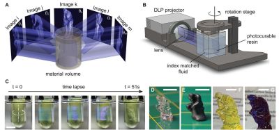
The technique is known as Computed Axial Lithography. The team describe the system as working like a CT scan in reverse. The 3D model geometry is created, and then a series of 2D images are created by rotating the part about the vertical axis. These 2D images are then projected into a cylindrical container of photosensitive resin, which rotates during the process. Rather than building the part out of a series of layers in the Z-axis, instead the part is built from a series of axial slices as the cylinder rotates.
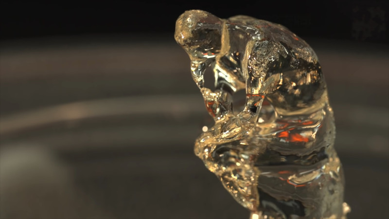
The parts produced have the benefit of a smooth surface finish and are remarkably transparent. The team printed a variety of test objects, including a replica of the famous Thinker sculpture, as well as a replica of a human jaw. Particularly interesting is the capability to make prints which enclose existing objects, demonstrated with a screwdriver handle enclosing the existing steel shank.
It’s a technique which could likely be reproduced by resourceful makers, assuming the correct resin isn’t too hard to come by. The resin market is hotting up, with Prusa announcing new products at a recent Makerfaire. We’re excited to see what comes next, particularly as the high cost of resin is reduced by economies of scale. Video after the break.
[via Nature, thanks to Philip for the tip!]


Isn’t “Tomography in reverse” == “Inverse of the inverse Radon transform” == “Radon transform”?
No. It is a drastic oversimplification to say that all tomography is just the inverse of the Radon transform. In particular, the Radon transform refers to a very specific ray geometry (parallel rays from each direction), which does not apply for point sources like this projector. If the point source is in open space (air), then you get what is called fan-beam or cone-beam tomography (depending on whether you just look at a single plane at a time, or at a 3D pyramid) — this is common in industrial CT, for example. In this 3D printing application, I suspect that the situation is even more complicated, since the rays actually refract at the air/glass interface as well as the glass/resin interface, which makes the ray geometry a lot more complex.
Finally, even in the parallel beam setting, it is really not helpful to think of tomography as the inverse Radon transform, since doing so leads you down the path of using filtered backprojection as the reconstruction algorithm. And that is an ancient method, which produces aweful results compared to modern tomographic reconstruction algorithms.
It looks like the bottle of resin is placed in a matching fluid and the only diffraction is at the first layer of the glass tank. Although I can “see” the bottle, so maybe not so much.
I would think a larger volume of resin will need a stationary container and a rotating projector. I wonder how they make their images, as in what model for the source. A grid of point sources and put together all the individual projections?
Yes, you can refractive index match the container and the resin if you can design your own chemistry. I am going to guess that the resin is also very viscous to minimize motion.
The camera model can be calibrated — you determine a unique ray in the liquid for each pixel, which you can do with camera calibration patterns at two parallel planes inside the volume. My research group did something similar for visible light tomography of transparent objects a good many years ago: PDF article.
Link: “Page not found”
Thanks to Google, actual link is:
https://vccimaging.org/Publications/Trifonov2006TRT/Trifonov2006TRT.pdf
Hmmm… a 3D printed version of what is in “Back to Video Basics with an ESP32 VGA Display”
The speed is impressive but they have a long way to go on quality. I also wonder if they will hit a physical size limit to what they can print
Dam hit that post button too early.
comment continued…
due to the resin not being 100% transparent.
100% transparent will not interact with the light, but you must be right. In order to react it can’t be transparent and if not transparent there is a thickness limit.
How does the inner part of the resin gets hard? In the figure it looks like if I project an image on the cylinder, then the outer layers of the resin should become harder, because the light is absorbed there.
Make the photo polymer very dilute, so the ray passes through almost unchanged… Then if you have a second ray crossing it the middle gets twice the dose. A third ray gets 3 times the dose with the edges getting 0 or 1 times the dose. The focus of the rays sets hard, the edges don’t.
Recycling the remaining liquid for future prints sounds tricky as it will be partially polymerised.
ok, so it really works only with clear resin :(
It won’t work at all with clear resin.
It may not cause partial polymerization. Most photosensitive catalysis have a threshold energy level that must be exceeded before they initiate. I would assume they are tuning the image strengths such that the NET energy of the intersecting images is necessary for photopolymerization. Several early attempts at stereolithography employed similar techniques. Several projects touting “Holographic 3d Printing” performed with similar methods have been attempted to varying degrees of success in recent years.
I’m not understanding how this works with just the one light source / projector that they are using. Wouldnt it at least partially harden the resin in the whole pathway of each light ray from one side of the cylinder to the other?
That is what I was thinking…
The photointiator requires X energy input over Y time to break down into an active state. If X is not reached within Y then the accumulated energy is insufficient to trigger the catalysis. Imagine if a glow in the dark substance is exposed to light….it takes on a a charge and glows until the energy it stored has diminished. In an avalanche reaction the PI can Glow over and over again rising in energy and shedding it off afterwards…..but if the energy exceeds X in Y duration then instead of slowly dissipating the energy the energy is released in a sudden burst and the polymerization reaction initiates. Meanwhile the adjacent molecule of Photoinitiator while very excited….glowing with potential….doesnt get that last little bit of X energy in time so instead of triggering it fades back down to its inactive state.
NOTE these substances do not NECESSARILY glow. This is all an oversimplification of an avalanche catalyst but hopefully it at least inspires understanding of this action a bit better.
Just looking at this, I’m wondering why this isn’t just hardening the edges of the cylinder?
yeah I wonder the same, but can only guess because it isn’t getting as significant of a cumulative dose as the center… the edges probably are polymerizing, but little enough that liquid shear (draining or rinsing the part) is still able to remove that without obvious problems (besides lower resolution).
the rotation of the liquid seems like it would lower resolution or deform the output, unless they rotate it with low enough acceleration (somehow analyzing the viscosity and ensuring the accel is lower than what it takes to move the molecules, static friction or something?). Rotating the light seems harder, but seems like maybe having the projector below the resin, with a few mirrors rotating instead? Let’s see if ASCII art fails here:
R \
/ /
^
let’s try that again, they removed my whitespace (R is resin, ^ is light source, / \ are mirrors, which would all be connected and rotate together):
R \
/_/
^
I think that after a short while the liquid and tank end up rotating at the same rate, but the time it takes would depend on the fluid viscosity, volume, and rotation rate (probably also on the adhesion at the glass-fluid interface).
They can use s-curve acceleration. But i guess it still needs some tuning…
https://www.youtube.com/watch?v=qYJpl7SNoww
Back in the good old college days 100 years ago (or was that 20) I first learned about the concept of 3d printing from a poster on the wall in my school’s technology building.
The poster described a process where 2 or more lasers were shined into a vat of resin. One laser was not enough to heat the resin to the point of hardening. Where multiple converged it would harden. The part could be drawn into existence by moving that point. I’m pretty sure this had to be done from the inside out but it certainly was not a layered process like we are used to today.
I thought that poster was describing something that actually existed at the time. Did/Does such a printer exist?
Yup, that’s called stereo-lithography.
“I’m pretty sure this had to be done from the inside out but it certainly was not a layered process like we are used to today.”
To clarify you mean that it was a cylindrical layered process instead of a planar layered process? If it has to be done from the inside out then technically its a layered process.
Reminds me of this laser acrylic engraving that you see in tourist destinations.
https://www.youtube.com/watch?v=EUpkZxisWzo
I’m still trying to grasp the critical range of thresholds for the printing to be finer in detail from a DLP projector in CAL without two beam sources. Seems better control ability with two or more beam sources… maybe the rotation and the timing of two or more positions effect on the resin from one beam source is what is effecting the resin in a controlled way where one position moment wouldn’t cure the resin.
In regards to the engraving process… reminded me of an explanation of this in glass/quartz too:
https://www.youtube.com/watch?v=sOrby692Uag
The resin market sure is hotting up.
Wonder if it’ll lower costs?
Can you use this to make objects with hollow core? (given that there will be channel to dain the uncured resin…)
I imagine that if you only projected edge profiles and not faces, yes. But purely by the method above, it seems like light overlaps, and thus cures the resin, all the way through the object.
The trick is to compute the intensity for each projected image such that the *total* energy deposited at each 3D point corresponds to the target (i.e either clearly above or clearly below the curing threshold). That’s what the “inverse tomography” does.