The must-have accessory on a modern all-singing, all-dancing amateur radio transceiver is a panadaptor. Inevitably driven by SDR technology, it’s a view of a band in the frequency domain, and it will usually be displayed as a “waterfall” giving a time dimension to see transmissions over a period.
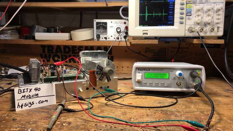
[Bill Meara, N2CQR] reminds us that panadaptors are nothing new, indeed that they date back to the first half of the last century and don’t even need an SDR to work. And to prove it, he’s produced one for part of the 40-metre amateur band.
The principle behind an analogue panadaptor is simple enough, it’s a normal receiver whose local oscillator is given a linear periodic sweep over the desired frequency band and whose output drives the Y axis of an oscilloscope whose X axis is driven by the sweep. In [Bill]’s case the receiver is a BitX homebrew transceiver, and the swept local oscillator is provided by his Foeltech signal generator. A neat touch comes in the ‘scope being synchronised by triggering on a marker frequency at the bottom of the range being swept. He’s created a video showing it in action, which you can see below the break.
There are quite a few routes into making this type of simple spectrum analyser, indeed some of us have tried ti with TV tuners.


A 555 will do it and an op amp or two. I did it years ago with a good car radio and the scope. SSI from the tuner’s detector chip, sweep to the tuner tuning voltage input. Later I used a converted medical scope that used a long persistence magnetic CRT. You will get a positive only display unlike the double ended display you see here.
I did it to an old brick cellphone too. 1G but I could see one caller pop up instantly on the whole band and spread the sweep and bias down to monitor on that single frequency in a second or so, much quicker than a scanner could assuming the band was otherwise dead clear. Use a 10 turn pot of course for the bias (tuning voltage).
It took me a long time to accept the math behind the fact that the fourier transform is basically just multiplying by all the frequencies. I like seeing an analog device that does it so directly.
Am I the only one who had never heard the word “panadaptor?” I’ve seen zillions of spectrum analyzers and radio things with spectrum displays, but who the hell calls it that? And why? What does it adapt?
I think a destination is a “panadapter” is a receiver accessory, which let’s you see a tiny bit either side of your receiver frequency. So you can see a nearby station, or empty frequency.
They do to back.to at least WWII, big and clunky, as were the receivers. Hard t o imagine so that in an airplane.
But there are variants. About 1972, Ham Radio Magazine ran an article where someone know when the lastused a free as display, and multiplexed about 7 signals onto it, for each HF ham band. So there were.seven receivers, each tuning 500KHz, so you see all the ban bands at once.
“Spectrum Analyzer” uses the same principle of scanning the spectrum, but tends to be a piece of test equipment. More precise, though a couple of decades ago with cheap varactor.tuners out of tv sets, they were seen more as a visual scanning device by some.
At one time I had the “wobbulator” out of one of those, which I used to build a panoramic adaptor. A wobbulator was basically a standard dynamic loudspeaker with the diaphragm replaced by a thin aluminum plate placed very close to another, stationary aluminum plate. Any AC signal applied to the “speaker” would vary the capacitance, and if the thing happened to be part of the LC tank of an RF oscillator, the output would be frequency modulated by the signal driving the wobbulator.
Use that signal for the local oscillator of a receiver and use the modulating signal to drive the horizontal of a ‘scope while the vertical was connected to the receiver’s AVC, and Hey! Presto! A panoramic adaptor.
I, no joke, read that as “pandaraptor” all the way through the article and well into the comments. I was looking forward to hearing the bizarre panda raptor story.