Coherers were devices used in some of the very earliest radio experiments in the 19th century. Consisting of a tube filled with metal filings with an electrode at each end, the coherer would begin to conduct when in the presence of radio frequency energy. Physically tapping the device would then loosen the filings again, and the device was once again ready to detect incoming signals. [hombremagnetico] has designed a basic 3D printed version of the device, and has been experimenting with it at home.
It’s a remarkably simple build, with the 3D printed components being a series of three brackets that combine to hold a small piece of plastic tube. This tube is filled with iron filings, and electrodes are inserted from either end. Super glue is used to seal the tube, and the coherer is complete.
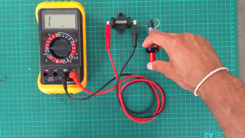
The coherer can easily be tested by measuring the resistance between the two electrodes, and firing a piezo igniter near the tube. When the piezo igniter sparks, the coherer rapidly becomes conductive, and can be restored to a non-conductive state, or de-cohered, by tapping the tube.
Coherers and spark-gap sets are fun to experiment with, but be sure you have the proper approvals first. Video after the break.


cool!
what is the name of the clockwork thingo with the loop of wire going through a coil?
That’s the piezoelectric igniter from a grill lighter or brulee torch. The spark generated between the two points of the igniter generate a brief RF burst.
I meant the device that came after this coherer
A multimeter
Multimeter.
Galvanometer, compass coil of wire….
I was thinking that the dvm was substituting for a galvanometer or similar instrument .
No multimeter (digital) back then…
:-)
for pitys sake!!!
I’m asking about the demodulation device that was a loop of wire, driven by clockwork, that ran through a coil
the thingo that was invented after the coherer!!!
anyone know what it was called?
nothing to do with this video!!
ok
found it
Magnetic Detector
https://www.youtube.com/watch?v=4CAxWoKD-fw
https://en.wikipedia.org/wiki/Magnetic_detector
“nothing to do with this video” is a pretty important statement in your question, you should have mentioned that in the first place. I was about to answer “multimeter”, just like “AC” and “Finn” because there is nothing else in the video to see. Then I realised you mention the most important part of the coherer based receiver, the de-coherer or decoherer (whatever spelling you prefer). There are several techniques that were used to act as decoherers
Electric vibrator: One method of providing the vibration necessary was to have an electric vibrator. This was mechanically linked to the coherer sufficiently to provide the mild vibration needed for it to act as a decoherer.
Clockwork vibrator: Another method of creating a decoherer was to use a clockwork mechanism. This had the advantage that it did not provide any additional electrical noise that would appear as interference. Systems for clockwork coherers included a cogwheel rubbing on a spring which was in turn attached to the coherer
Relay actuator: This was probably the most advanced and usable form of decoherer. It used a scheme whereby once the signal was received, and the coherer started to conduct, not only did this create an audible sound via a sounder, but it also operated an actuator that knocked the coherer and cause it to decohere. In this way the decoherer operated only once a signal was received and re-set it almost immediately to receive a further signal.
Te reliably coher and decoher is an interesting challenge, the clockwork concept is the most “noiseless” version as it does not generate any RF when decohering, but the problem with clockworks, is that they need to be wound from time to time. Something easily forgotten…
I hope this answers your question?
Regenerative an crystal, then transistor where radios I’ve built. Not spark gap. I did at least learn something about an old part from yesteryear…
Good post thanks…
You are thinking of the magnetic detector
that’s the one
it came right after the coherer
I must be getting old!
listening to modern AM broadcasts with a magnetic detector is very cool
I saw a vintage one playing ABC’s Radio National broadcast when I was really young, I could never get someone to tell me how it actually worked
I’d built a few “crystal” radios, but this thing with a couple of magnets, a coil and a moving loop of wire seemed like voodoo
Thanks to you all!
This conversation made my day XD
(The propability that a HAD reader doesn’t know how a multimeter looks like is rather low – imho…)
I was wondering what to make the moving wire out of
I’m thinking if my two pulleys have a large enough diameter I could get away with “handy wire” soft soldered
ohhh… you meant “maggie”… yes that is an interesting concept.
If you want to make one yourself, I guess that regular audio tape or video tape perhaps might be fun to try. However if you want to make it look authentic then the modern tape is not an option.
PS: funny how the timeline on the hackaday comments get screwed up. When I posted my comment (7:40) about the decoherer, your comment about maggie (6:59) wasn’t visible to me, despite the fact that there are more then 40 minutes between them. Impossible to have a comment conversation this way. I hope they fix this, very confusion when reading it back.
do you think magnetic tape would work?
I was thinking of a draw plate to get some iron wire really fine
a loop of wire through a coil bobbin is going to be a bitch to make
coherer’s are fun, played with them as they are indeed quite easy to make.
No need for printing, an old ballpointpen could even be enough to serve as the tube. A transparent pen/tube is only required so that you can see what you are making. The 3D printed method here is a very nice design and it’s very nice to see it here on hackaday.
Regarding radio and coherers, the difficulty lies in automating the tapping and getting some decent range out of this thing. SInce the ‘tapper’ might generates some sparks to that trigger the coherer. Though they managed to do it in the past, so it should be doable now, though I tried it and failed… should have tried harder. I’m hoping that someone will be doing that as nicely as shown in this project here.
Thanks for posting, considering that the coherer technology is a important historical part that still holds some mystery about the way it really works. Feel free to comment on that one…
I suddenly find myself wondering whether a FET driven piezo actuator of some sort could be made to actively de-cohere the coherer upon receipt of signal, in a similar fashion to the older relay-driven system you mentioned in your well-written answer to [cyberteque]. My thinking is that the FET could replace the relay and wouldn’t generate any RF upon switching, and the piezo actuator (if such a device exists or could be made) would be able to knock or vibrate the coherer without the RF spike that is a potential issue with using a solenoid.
If none of this makes any sense, please ignore it. I tend to get into these weird mental ramblings sometimes.
hmmm… that’s perhaps not such a bad idea. Though the trick is to do it all with parts that were also available 100 years ago, because otherwise it would be cheating. But I like the way you are thinking and since piezoelectricity (according to wikipedia) was discovered in 1880 this may still count as a usable solution (partially).
Thanks!
Using technologies available at the time would certainly increase the challenge. I wonder how difficult it would be to homebrew a working piezo crystal from scratch. I suppose that finding the quartz shouldn’t be too hard in most parts of the world, but making it work properly for this application would probably take quite a bit of research and experimentation.
Okay, no FETs, but semiconductors were a known technology (I’m thinking about some of the work done by Sir J.C. Bose, who managed to make some naturally occurring semiconductors work as LEDs at the beginning of the 20th century, if memory serves) at the time that coherers were in use, so again it might be possible to homebrew something up with a large amount of time and effort. Would be an fascinating project, but I’m not sure that the end results would be worth the huge amount of effort needed to get there!
I’ve gotten quartz crystals to oscillate, put a plate on opposite faces and use the bog standard CMOS NAND gate circuit, you need a few ceramic caps to knock the Q down a bit
we got a big crystal, about 80 mm across to oscillate, excited them with an audio generator, “whack” them and see a few hundred volts
really cool thing with the big crystal in our holder, we split a HeNe laser beam with microscope slides, bounced it around the living room on SLR mirrors, shone it through the crystal across all three set of faces, onto a screen, then excited the crystal with audio from the stereo, lit a couple of packets of incense to fill the room with smoke
great experiment after a “few” beers!
Could there actually be an application for this as some sort of super simple lightning strike detector? Just a thing that popped up in my head. Never mind…
Done in the last decade of the 19th century by Popov. so, yes:)
Popov used a coherer for this very purpose in the late 19th century so, yes it can.
As a shunt to ground … Would be a great idea if it work work
Sorry… Should have finished my thought.
If it would work, use it as a shunt to ground to protect equipment (such as amateur radio gear) from lightning damage.
At last–a video is exactly the right length! Short, and to the point. No long introduction, titles, or rambling voice-over explanation.
Not to forget the awkward music… :)