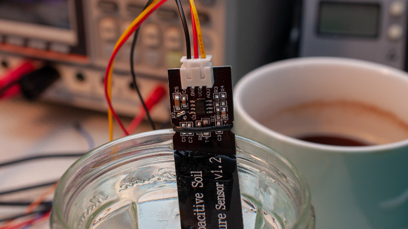
A frequent beginner project involves measuring soil moisture levels by measuring its resistance with a couple of electrodes. These electrodes are available ready-made as PCBs, but suffer badly from corrosion. Happily there is a solution in the form of capacitive sensor probes, and it is these that [Electrobob] is incorporating in to a home automation system. Unfortunately the commercial capacitive probes are designed to run from a 3.3 V supply and [Bob]’s project is using a pair of AA cells, so a quick hack was needed to enable them to be run from the lower voltage.
The explanation of the probe’s operation is an interesting part of the write-up, unexpectedly it uses a 555 configured as an astable oscillator. This feeds an RC low pass filter of which the capacitor is formed by the soil probe, which in turn feeds a rectifier to create a DC output. This can be measured to gain a reading of the soil moisture level.
The probe is fitted with a 3.3 V LDO regulator, which is simply bypassed. Measurements show its output to be linear, so if the supply voltage is also measured an accurate reading can be gleaned. These probes are still a slightly unknown quantity to many who might find a use for them, so it’s extremely useful to be given this insight into them.


Oh, I need this! I have a housemate who complains if the porch plants dont get watered every day, and I am going to integrate this with the home automation system so there is no debate about when it needs to be done. 😁 Thanks for the tip!
Depending on what your specific needs are, there seem to be ready made versions with this sensor attached to an ESP8266. However, I don’t know the details of how they are built and how long the battery will last.
It seems that I was using this sensor wrong. Thank you [Electrobob] and [Jenny] for sharing this.
how were you using it?
Exactly as you wrote – by powering it from two AA cells.
Capacitance is cool but using the proper frequency resonnance is better ;)
Really cool papers about moisture/salinity on the same capacitance probe.
https://hal.laas.fr/hal-01925585/file/JST-A%20new%20bi-frequency%20soil%20smart%20sensing%20moisture%20and%20salinity%20for%20connected%20sustainable%20agriculture.pdf
https://hal.laas.fr/hal-02015850/document
That also sounds interesting.
Something I was pointing in the article is that it would have been simpler on the sensor side to have a simple oscillator and count the frequency, but it is a bit more difficult to count frequency (at such high values) with generic arduino boards. Arduino users are probably the intended users of the modules in the article.
I am not sure how relevant salinity is for house plants, any thoughts?
“Salinity” can refer to all sorts of dissolved ions, which basically make the soil a leaky capacitor and makes it seem wetter than it really is.
That is a good point, indeed in this circuit more dissolved ions will act like a wetter soil.
On the other hand, considering my situation (house plants) I would suppose the dissolved ions don’t change that much.
I suppose you add fertilizers occasionally?
The PIC1654 was used as frequency counter up to 65MHz with minimal external components.
A few MHz is possible on the AVR with Timer2 async mode.
e.g. http://www.avr-asm-tutorial.net/avr_en/fcount/fcount_m8.html They use a 4-bit ripple counter to extend the range from 10MHz (prescaler=1) to 40MHz (prescaler=16).
Yes, but the target audience of such commercial sensors is arduino users, so whatever the output is, it should work with the majority of the boards. That is why it uses a simple analog output, at the cost of a few passive components.
I am sure in a way most dev boards do have some frequency counting HW inside the micro, but that is more inflexibly tied to a specific pin and timer, requiring different constraints.
A worthy hacker won’t try to limit the solution.
If you can’t depend on the Timer, then include your own uP with a timer. Re-read my post.
Here’s a practical circuit for using high frequency with common uCs:
http://tinyurl.com/y5g6n5nb
1) take the oscillator clock out of your uC (fuse setting on AVRs) and you have at least 8 MHz at your disposal.
2) the output of a 50/50 duty cycle clock signal tends to average at half Vcc, so you can choose whether to follow the peak or the bottom of the resulting waveform
3) In this circuit – a precision peak follower using schottky diodes – the circuit is flipped to follow the bottom of the waveform because then you can use cheap op-amps with limited common mode / input range properties. e.g. bog standard LM258
4) the output voltage is between 0 – 1/2 Vcc in the range of 2 – 300 pF
5) Pair this with a ATtiny85 and you get a compact sensing system that can be turned into an I2C device for stringing up 128 units along a single cable
I didn’t have a problem with corrosion on a resistance based sensor over a 6-12m period.
I found the sensor was a continual current drain, which was a major issue for my battery life. I therefore ran it from a spare pin, and turned it off other than when the ESP01 woke every hour to take a reading. I suspect this also saved it from corrosion.
Powering it down has saved it.
Keeping DC off the sensor conductors is the way to go for sure. My off-grid homestead that collects rainwater struggled for years with all the available water level sensors that failed young in various ways, from sticking floats to corrosion, until I adapted a scheme shown in a very old National Semi Apps handbook. I “drive” the tank with the output of a 555, around 12v pk pk at around 50khz (not critical) via a coupling capacitor – NO DC – and sense the level with a few wires coming down from the top of the tank, various lengths, each connected to it’s own little AC coupled 2 diode, two capacitor voltage doubler, and that drives some arduino logic inputs (also works on esp8266). Simples. I use titanium wire (McMaster), the driver wire runs along the bottom length of the HDPE stock tank I use, the other wires just stick down through holes in the top. Finally – after years and years (I’be been off grid since ’79) – this is the one the works.
I’d sat the above is entirely plausible and yes, you should be able to get some sort of analog indication – I needed really precise points for my application so I could know when to open valves, when to flag “it’s time to conserve water” and so on.
Note this works regardless of the water purity (even deionized distilled water will work), because it is measuring the capacity – and water has a dielectric constant around 81, a lot higher than air. It’s just a matter of getting the speeds and feeds into a good range.
There’s a little more info here: http://www.coultersmithing.com/forums/viewtopic.php?f=59&t=1119&start=0
That sounds smart. I have seen the technique of AC coupling (remember some 555 circuits about this), but never actually driving the tank. Thanks for sharing.
Have you thought about ultrasonic? There are quite a few modules available.
I just had a really weird thought about how to sense water levels: have two pipe that go down into your tank. One goes 50%(?) of the way down and is capped off at the bottom. The second goes all the way to the bottom and is open at both ends. When you want to check the water level, have compressed air blow across the tops of both pipes, producing tones. (The set-length pipe is there to act as a control.) The pitch of the open-ended pipe will change depending on how much water is in it, therefore telling you the water level. If you don’t have compressed air available, then a piece of rubber slapped on the end (like the Blue Man Group uses) would produce the required tones. Is that crazy enough for you? :grin:
What about simply gluing a humidity/temperature sensor inside a small cup, then burying it upside down in the soil? Would that not work? If not, why?
Are you talking about the sensors that are used for air?
Those would not work, they are designed to measure relative humidity of air. Many of them do not like condensation on them – when the humidity reaches 100%. You will get that very often as the soil is heated by the sun and there will be evaporation.
Ah. Fair enough. Thanks for the reply.
I measured a few more sensors. Variability seems reasonably low. Check original article.
Did some backyard tests over the summer and the reg removal worked well with our 3.3v ProMini loggers & the stock ADC. With a few more modifications you can put the probes capacitance on the other side of the 555 – converting the sensor to pulsed output:
https://thecavepearlproject.org/2020/10/27/hacking-a-capacitive-soil-moisture-sensor-for-frequency-output/