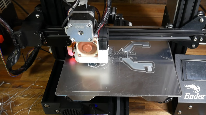
In 3D printing, we often talk about leveling the print bed, although that’s not an accurate term. A bed that is level in our terms presents a flat surface that is parallel to the path of the print head, but within reason we care little about that. Instead we care more about it being parallel to the path of the head than it being perfectly flat. If we had a perfectly flat bed — say a sheet of glass — you’d think it might be pretty easy, but for some other materials it could be convex or concave or even have ripples all over the place. [Teaching Tech] shows you how to manually “level” the bed using a mesh but without using an automatic sensor. You can see the technique in the video below.
When you use adjustments to level the bed, you are tramming it, but only the very pedantic use that term for fine adjustment. But no amount of adjusting bed springs will get rid of bulges and ripples. A common solution is to use a sensor to measure the distance to the bed and form a mesh correction. Then, as the printer head moves in the XY plane, the software will adjust the Z-axis to rise over bumps and go down if there is a concave portion of the bed. What [Teaching Tech] is doing, however, is a manual mapping. You won’t need to add a sensor to your printer to take advantage of the method.
The technique does require — probably — reflashing your firmware, and the firmware he uses appears to be Marlin. However, Repetier and perhaps other firmware does this too. The LCD bed leveling option makes it pretty trivial to do the actual work, and once you compute the mesh, you shouldn’t have to do it again. Essentially, the printer will probe multiple points and pause, allowing you to adjust the head using the usual piece of paper.
Each time you make the adjustment, the printer remembers the height adjustment and then uses the collection of different heights to build up the correction mesh. This is essentially the same process that occurs with a probe except your manual adjustment is standing in for the probe data. You shouldn’t need to do that very often as long as the shape of the bed doesn’t change.
If you can update your firmware, this is a cheap way not to have to add a Z probe to your printer. Then again, adding one isn’t that expensive, and then the whole process is automated. That automation makes it easy to recheck it or even run it before each print if you like.
There are lots of other techniques. A force-sensitive resistor can be shared among printers, for example, and would actually work with this technique if you have a serious bed problem. If you mill PCBs, you might run into the same problem, and there’s a very similar solution.


Can one simply print a web of suitable thickness that spans the bed mounting points and use the resulting print as a shim beneath the bed?
It’s generally called a raft. Rafts tend to make up for a wonky bed
That may work if the bed was perfectly flat and X/Y travel was perfectly planar, but if a bed was perfectly and X/Y travel was perfectly planar, then a screw on each corner of the bed would leave it perfectly. If your bed is not perfectly flat, or the X/Y travel was perfectly planar, then shims (or adjustment screws) wouldn’t help (possibly if the bed was flexible, but if the bed isn’t ridged there will be other problems).
It’d be a good idea if beds weren’t usually 5mm of aluminum and 3mm of glass. No way of bending that. I can see that being made of ABS if you mostly print materials that need less than 120°c bed temp.
What I do is buy sheets of normal 3mm glass cut to size, in a regular glass pane shop, even cut down to 220×210 with chamfered corners they charge me ~$1.50 for each lol. They are usually good enough for usage without bed leveling, although i’m far too lazy to keep the bed correctly parallel. buy 2 or 3 of those and one is almost guaranteed to be good enough. so far doesn’t seem to have any problems with abs temps or anything, although i did have the usual bad experience with PETg
My printer/CNC has a dual head that can print and or mill. A forth axis adjusts the height of the print head relative to the mill. Wherever I need to “level” the print surface, I just mill it out. I’m surprised it is not more common. It is real handy to be able to drill and print in the same machine. There are some features a printer can’t make with great precision that need to be milled and vice versa.
When in doubt, mill it out
Well obviously that only works if you have a milling attachment. I did the same with my ShapeOko 2 and a nice spoilboard cutter. Run the cutter around the whole spoilboard and poof – instantly leveled bed.
What do you mill though? Do you just add aluminum sheets to it or something like that? Also, does it have a heated bed too?
I agree it should be more common, but I think there are two things holding it back. First is cost, a mill needs to be a lot more rigid than is necessary for a printer, which adds a lot of cost. Second is software, in my experience CAM software requires a lot more user planning and knowledge than slicers.
A few years ago I did some experiments with printing on PIR foam instead of a smooth bed surface. The technique was to bury the nozzle about 1 mm in the foam and let it create its own flat/trammed surface by printing a raft for the first layer- no milling needed because the nozzle can push into the foam. Molten plastic sticks to PIR, and the PIR doesn’t break down at nozzle temperatures. The foam comes in 4′ x 8′ x 1″ sheets for $15 at Home Depot, so it’s dirt cheap, you can cut it with a razor knife, and it can be reused several times with a quick sanding between prints. You could use a light duty milling head to smooth out the used foam surface between prints. No heater, no glass, no glue, no tramming required- just set an offset at the start of the print to ensure the nozzle is in the foam.
ABS printed directly on the foam, without a raft: https://vimeo.com/66558877
I think it would be an excellent technique to use for a portable printer, if anyone ever needed a portable printer. Eliminating the bed heater greatly reduces power required to run the machine. It would also be good for a very large volume printer where obtaining sufficient power for a large bed heater would be a problem (home type wiring is typically limited to about 2kW per circuit in the US). It would also keep the bed mass very low in a large volume printer, so easy to lift with a small motor.
“2kW per circuit in the US”
Wow! I couldn’t manage with this rating, don’t you have kettles, arc/tig welders or crepe machines?
We do, for larger needs we run dedicated circuits. Also we use 110/220V services for residential use, so smaller applications use the 110VAC with a 20 or 15 amp circuit breaker, and larger things like electric stoves will use 220VAC with a 50 amp circuit breaker.
What is the problem with just getting a flat bed? It seems that this should be possible even with just a fly cutter on a cheap mill…. Am I missing something?
In other news, I really think mesh leveling on my mattress would greatly improve my sleep experience but I don’t think my back supports firmware updates…
Not perfectly even heat + two or more dissimilar materials = warping
If I had myself a mill, I’d mill my printbed flat with the heater attached and at temp to take into account thermal effects.
For now I have to make do with the BLTouch sensor beeping around after the printbed is up to temp.
I wonder if it is possible to drill some mounting holes into a sheet of 5mm borosilicate glass to mount directly in place of the aluminium plate print bed I currently have?….
Why not just hold the glass on with binder clamps like the rest of the world. The neat thing with that setup is if you are careful you can remove the binder clamps and the piece you just printed on the glass, scrape the piece off the glass, and carefully replace the glass and binder clips without messing up the bed level. If you have a bunch of pieces to print this can save you a lot of time if you are careful.
Personally, I just used a dremel and some thin steel to make clips that attach using the existing corner bolts. The glass sheets just slide into place and don’t budge; it takes a bit of force to remove/place them, but that is what I want.
I tried the binder clip thing, but the glass tends to flex to conform to the slightly warped bed underneath.
I figured that using a piece of flat glass with decent thickness, then sticking a thin sheet of magnetic stainless steel to it to allow for a removable magnetic print surface would make for a nicely flat print bed.
My other idea was to get a chunk of precision surface milled magnetic stainless maybe around 6-8mm thick, and use that with a removable magnetic print surface.
I’m using the removable magnetic print surface now and I love it, but not the warped aluminium print bed so much.