LED cubes are mesmerizing and fun, but they’re usually a pain to build. Not so with [burkethos]’s cleanly designed cube.
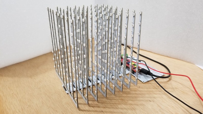
Many cubes are put together in an elaborate sculptural style. Traditionally the leads of the LEDs are artistically bent and then hours are spent laboring over the future rainbow Borg cube. This build is more reminiscent of a motherboard or back plane design. The LEDs are surface mount units re-flowed onto a rake shaped PCB. At the base of each “rake” there’s a right angle male header. This is then soldered to base board which creates a reliable mechanical bond.
There are some downsides to this approach. For example, the PCBs occlude the LEDs at some viewing angles. However, this can be mitigated with careful placement in the room, or in one variation, mounting the cube at a different orientation so the rakes are horizontal rather than vertical.
Regardless, we appreciate this new take on an old project and can definitely see it having a more universal appeal than the kits that require a couple weeks of afternoons to finish.


the designer might consider creating the PCB board which narrow between the LEDs with only 2 traces on top and 2 traces on bottom( 2 sided board ) and allow for the LED runs to be horizontal with maybe 4 verticals at the corners.
This way there’s a minimum of visually obscuring going on and by using a dab of hot glue on each LED the light would be diffused and also view able from most angles.
Agree with trimming the size of the PCB. Could also go with a thinner PCB vs the standard 1.6 mm and have one more board tying the open ends together if needed for additional stiffness. I almost always go with 1 mm or less these days. Also, you can get WS2812 type LEDs in the normal 5 mm bullet shape, which would drastically increase the viewing angle.
But what an awesome idea for simplifying the process of building an LED cube! I’ve wanted to make my son one, but it always seemed too daunting. Definitely doing it now.
I googled for defused smt ws2812 but only found thru-hole versions.
The OP was having problems getting alignment correct and a basic 3D printed part could be used to align and hold the PCBs while soldering. And while using .1″ headers is nice I would think soldering the 90 degree connections like the FR4 Machine Shield did would be quicker and easier if built onto a base. https://www.kickstarter.com/projects/1090944145/fr4-machine-shield
This project is tempting and I looked for KiCAD files but saw nothing open sourced. Easy enough to build up though and probably should get another board under my belt since it’s been too long since my last. Might also be a good project for toaster oven soldering task.
Be careful with the WS temperature profile – check the data sheet first!
Here are the ones I was referring to. Not SMT. I’ve used these a few times when I wanted more unidirectional light. They work exactly like the common SMT WS2812Bs:
https://www.ebay.com/itm/APA106-F5-5mm-RGB-LED-50pcs-compatible-with-WS2812B-or-SK6812-NeoPixel/254374271722?hash=item3b39e35aea:g:oagAAOSwvENcDhHv
I highly recommend diffusing the light from each LED. Perhaps with ping pong balls that have openings at the top and bottom to slide down each PCB, glued at each LED. This will accomplish two things:
1) Provide 360 degree light at each LED, giving the intended effect from almost all viewing angles.
2) Make a much softer, less intense Lighting. Looking at bare LEDs, especially head-on, can be really unpleasant.
Also, could the PCBs be double sided? (Same pixel signal routed to each pair of back-to-back LEDs, same number of total pixels)