Look, if something happened to you every three weeks or so to basically turn you into a different person and factored heavily into whether any new humans were created, you’d probably want to keep abreast of the schedule, yeah? Yeah. So, while there are, of course, a ton of ways to do this with your phone, most of those apps do gross things with your data. Are you angry yet?
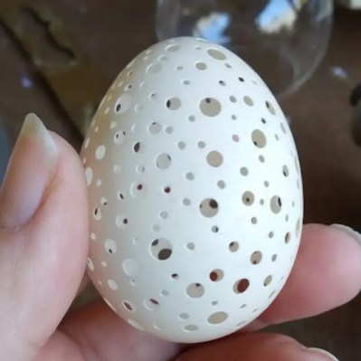
The coolest part is that this is an actual egg from one of [Jakoba]’s backyard chickens. No. The coolest part is how she was able to make so many holes without breaking it. (It took four tries.)
After bleaching the insides, the egg was ready to glow. As [Jakoba] says, the guts are simple — just a Wemos D1 Mini ESP8266, a WS2812 LED, and a heatsink. The enclosure consists of an inverted peanut bowl with a glass ornament hot-glued in place.
Once it was put together, all she had to do was add it in Home Assistant and use the current calendar state to trigger services from the YAML configuration.
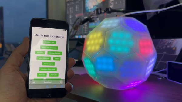
Although disco music and dancing may be long dead, the disco ball lives on as a staple of dance parties everywhere. [Tim van de Vathorst] spent a considerable amount of time reinventing the disco ball into something covered with RGB LEDs that reacts to sound and uses a color sensor to change hue based on whatever it’s presented with.
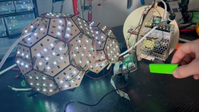
[Tim] started by modeling the disco ball after a soccer ball with a mixture of pentagons and hexagons. Then it was off to the laser cutter to cut it out of 3mm plywood sheets. Once assembled, [Tim] added LED strips across all the faces and wired them up. Then it was time to figure out how to hold the guts together inside of the ball. Back to the drawing board and laser cutter [Tim] went to design a simple two-piece skeleton to hold the Raspberry Pi and the power supply.
In order to do some of the really interesting effects, [Tim] had to make sure that the faces were divvied up correctly in code. That was difficult and involved a really big array, but the result looks worth the trouble. Finally, [Tim] covered the ball in white acrylic to diffuse the LEDs. As you will see in the build/demo video after the break, the ball turned out really well. The only real problem is that the camera doesn’t work very well without light, which is something good parties are usually short on. [Tim] might add a spotlight or something in the future.
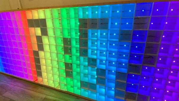
We’ve all got one: a blank space somewhere in our home that we don’t know what to do with. [James Miller] had one above his kitchen cabinets, so he filled it with a giant LED matrix. The result is a large but surprisingly attractive LED screen that can send messages, provide illumination, or while away the idle hours of the night playing Conway’s Game of Life.
[James] built the matrix using the usual suspect for these builds: several strings of WS2812 lights . He initially ran this from a Raspberry Pi, but realized that there was no need for such a dizzying amount of computing power, so he switched to an ESP32 instead. The frame is built from wood and foam board.
The first version he built used a fabric diffuser, but after a close encounter with a flaming steak, he switched over to commercial ceiling light diffusers cut down to size. We might have been tempted to keep going and try an “egg crate” style ceiling light panel for a the smaller pixel size, but [James] thinks he has reached the “good enough” point of this project. It’s certainly a fun build, and it looks very cool with minimal materials.
Fibonacci numbers are seen in the natural structures of various plants, such as the florets in sunflower heads, areoles on cacti stems, and scales in pine cones. [HackerBox] has developed a Fibonacci Spiral LED Badge to bring this natural phenomenon to your electronics.
To position each of the 64 addressable LEDs within the PCB layout, [HackerBox] computed the polar (r,θ) coordinates in a spreadsheet according to the Vogel model and then converted them to rectangular (x,y) coordinates. A little more math translates the points “off origin” into the center of the PCB space and scale them out to keep the first two 5 mm LEDs from overlapping. Finally, the LED coordinates were pasted into the KiCad PCB design file.
An RP2040 microcontroller controls the show, and a switch on the badge selects power between USB and three AA batteries and a DC/DC boost converter. The PCB also features two capacitive touch pads. [HackerBox] has published the KiCad files for the badge, and the CircuitPython firmware is shared with the project. If C/C++ is more your preference, the RP2040 MCU can also be programmed using the Arduino IDE.
This video two-part build log shows a lot of woodwork, with a lot of mistakes (happy accidents, that are totally fine) made along the way, so you do need to repeat them. Essentially it’s a simple maple-veneered plywood box, with a thick lid section hosting the display and some repositioned speakers. This display is taken from a standard LG TV with the control PCB ripped out. The power button/IR PCB was prised out of the bezel, to be relocated, as were the two downwards-facing speakers. The whole collection of parts was attached to a front panel, with copious hot glue, we just hope the heavy TV panel was firmly held in there by other means!
As an introduction to embedded electronics and programming in a straightforward environment, there isn’t much out there that can hold a torch to the Arduino Uno. Cheap (especially if you count the clones), easy to find, and quick to deploy, with countless support libraries, it’s a go-to for many a hack. This scribe simply can’t remember how many he’s bought, hacked, and deployed over the years. But can it be improved? [John Loeffler] thinks so, and his 2023 Hackaday Prize entry, the Uno Plus+ could be the one.
After clearing the top deck of extraneous components (by shoving them on the bottom) there was much more space to expand the header labeling, so there can be no accidental misplacement of those DuPont wires this thing will inevitably sprout randomly.
The board also has an additional Stemma/Qwiic connector and a Neopixel LED for indication duties. Also sitting on the PCB bottom are a ton of opamps, to drive the header indicators. Yes, this board has a full set of colour-coded LED bling indicators, showing the logical state of each and every pin on all headers, giving an easy way to check the desired activity is occurring. Plus it looks cool. Illuminated headers? YES!
Think the Uno too light on resources to perform any meaningful modern workloads? Think again!
[Koraks tinkers] was gifted a gargantuan photographic enlarger, a Durst Laborator 138 s, which is a unit designed specifically for black and white usage only. This was not good enough for [Koraks] so down the rabbit hole of conversion to colour we go! The moral of the story is this: if you can’t find it, build it. The hacker mentality. After wasting time and effort trying to source a period colour head for the thing, [Koraks] did the decent thing and converted what was already in front of them.
Now, if you’re thinking this process is simply a matter of ripping out the tungsten bulb and sticking a high-power RGB array in there, then you’re going to be disappointed! You see, colour photography of the era — specifically the RA4 process in this case — requires careful colour calibration and is heavily biased towards the red end of the visible spectrum, due to the colour curve of those tungsten bulbs we touched upon earlier.
The first attempt at using an off-the-shelf COB array was a bust — it simply wasn’t bright enough once the light had passed through the diffuser plate, and the light path losses were too high to expose the RA4 paper sufficiently, especially at the red end of the spectrum. Quite simply this is due to the reduced energy of red photons (compared to blue) making the desired chemical reaction rate too low. The solution is more power.
Another issue that quickly raised itself was that 8-bits of PWM control of the RGB components was inadequate since the ratio of blue to red required was so skewed, that only a few effective bits of blue channel control were usable, and that was far too granular to get the necessary accuracy.
[Koraks’] approach was to custom build an LED array with twenty red 3W LEDs and eight each of the green and blue devices. 12-bits of PWM resolution was delivered via a PCA9685 PWM controller, that also handily controlled the cooling fans. The whole thing was hooked up to an Arduino Nano, with an MCP23016 expander board performing the duty of interfacing the rotary encoders and trigger footswitch. In fact, several iterations of the LED array have been constructed and this four-part blog series (Part1, Part2, Part3, Part4) lays out the whole story in all its gory detail for your entertainment. Enjoy!