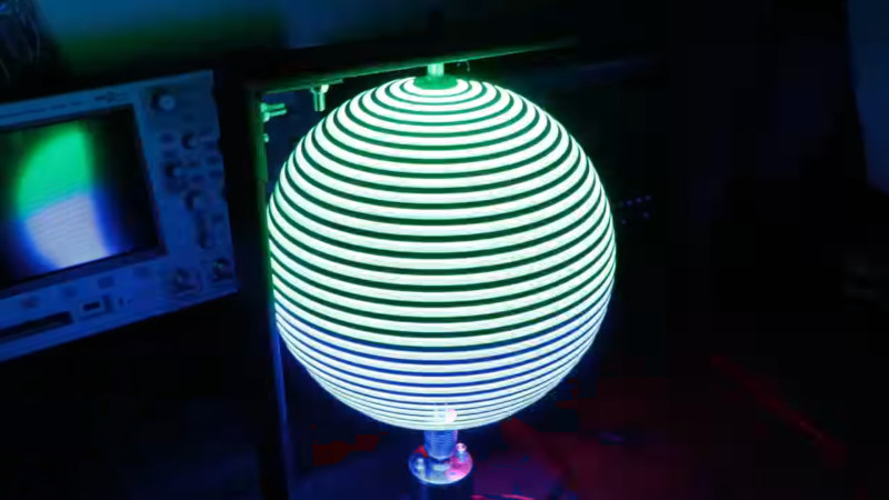
POV builds come in all shapes and sizes, and typically rely on LEDs for their high light output and fast response time. With this in mind, [Great Scott] grabbed some LED strip off the shelf and set about whipping up a POV LED globe.
Being a spinning POV build, it’s necessary to consider how to get power to the rotating elements. [Great Scott] decided to go with a simple solution of putting a LiPo battery on the rotating assembly, which runs the LEDs and Arduino Nano at the heart of the operation. The LEDs in question are of the APA102 type, making them readily addressable and capable of a wide color gamut. It’s all spun by a simple brushed DC motor, running from a separate supply at the base of the platform.
It’s very much a hacker build, held together with duct tape and zipties. Despite this, it looks tidy when in operation, as all of the important hardware is hidden at the centre of the globe. There’s a bit of a vibration problem, but [Great Scott] reckons this can be fixed with some frame modifications.
We’d love to see the build run some more advanced operations, like a representation of the Earth, or some kind of sun clock. If you’re interested in learning more about POV displays, we’ve got the primer you need. Video after the break.


Been done years ago
https://www.instructables.com/id/POV-Globe-24bit-True-Color-and-Simple-HW/
so?
Been done years before that :P
http://orb.jamesnsears.com/projects/orb/
A treaded hole in the main shaft would allow you to use a small length of threaded rod to adjust out the imbalance.
Yeah, with a hacksaw, drill and self locking nuts putting a captive nut at the end of the rod would have been pretty easy. I think an article on passive self balancing mechanisms, like used in washing machine would be neat. I tried searching hackaday for one and couldn’t find any.
Good idea. Locking the treaded rod to the shaft with locknuts would remove the need to thread the hole.
The threaded rod could then be positioned as a course adjustment and a third locknut along the treaded rod could then be used as I fine adjustment.
Would you please elaborate? I am not very good to image a passive self balancing mechanisms. Do you have any links?
If I understand correctly they are basically a hollow ring with a viscous fluid and baffles, 2 or more ball bearings, or radial pendulums inside.
Because of this you might notice a sloshing or clanking if you manually turn a front loading washer drum, even when empty.
The keywords, “LeBlanc Balancer” and “washing machine balance ring” seem to be a good starting places for research.
Ball bearing balancer simulation:
https://www.youtube.com/watch?v=HEiHRpPgRgU
A paper on leaky baffle segmented ring liquid balancers:
http://downloads.hindawi.com/journals/sv/2013/742163.pdf
Thank you!
What if… you had multiple concentric rings inside each other (but offset so that the LEDs on the inner rings weren’t blocked by the outer rings). Would you be able to make a 3D display?
Interesting thought. I was contemplating making one of these spinning globes into an oscilloscope display. It could be interesting to have them with a slight offset. Or perhaps have them spinning on different axis.
If the offset angle is small then there will always be a position where the outer ring obstructs view of the inner.
With two rings 180 degrees apart there will be no visible obstruction as the other LEDs are facing away anyway.
With three rings at 120 degrees apart the obstruction would be at the sides of the viewed POV display where it is less noticeable.
I should have said arcs instead of rings.
The globe could have a “park” position to recharge and load up new surface features. Mod via radio?
Love the 3d idea.
Interesting. I just recently assembled a single color POV sphere that I got from aliexpress:
https://www.aliexpress.com/item/32816427792.html
One clever design they used is wireless charging technique so the spinning part needs no battery. I also modified it using ESP8266 so it became wifi capable.
a simple slip ring is a far better way to power it than a battery
The challenge with slip rings is that the rotation speed is limited and those that can spin fast are very expensive. The wireless charging coil method completely removes the need for electric connection between the base and spinning part and is relatively cheap.
Super.
At what surface definition does processor speed and memory become a limit? (gedanken, however that’s spelled)
Already!
The atmega328 only has 8kB ram which would be about a column of pixels every one degree at a color depth of 8bpp or 256 color.
There is already a noticeable pixel update phase distortion due the the fact that the LEDs are being updated in serial.
This could be fixed with better per led update synchronization with a faster uc.
I get the simplicity of construction and the appeal of symmetrical design but if you offset the leds of the two arcs of the circle, instead of placing them in alignment with their mirror, you can fill in the missing bands and up the effective resolution of this display…..though you may have to double your rotational speed since you wont be overwriting anymore.
You don’t have to double the rotation speed ad the frame rate is still the same.
You may however need to improve synchronization if there’s a visual offset in the display.
As built ONE rotation traces the image TWO times….So if the speed is 900rpm then you get 30 images per second…and it should look pretty stable but be banded due to the symmetrical alignment
Built as I propose ONE1 rotation traces a SINGLE higher resolution image…So if the speed is 900rpm then you get 15 images per second and it should flashing noticeably but it it should be able to produce a perfect sphere without gaps between bands.
Double the speed as I originally said may be necessary and at 1800 rpm you will have a fairly smooth 30 images per second
https://www.instructables.com/id/Make-Your-Own-POV-LED-Globe/
He only has LEDs on one side of the circle. The other side of the circle is used for the hall effect sensor.
The motor is 3000 RPM so the frame rate is 50 Hz.
A second column of LEDs on the other side would result in a 2:1 interlaced frame rate of 50 Hz.
Are you looking at the video of the globe posted here? Did you look at the link you just posted?
He has a full circle of leds. BOTH ARCs. all 360 degrees (okay he doesnt have the shaft points but you get mine)
he has 72 Leds on each side of the axle. They are aligned to form 36 rows that are double scanned each rotation
as the first 72 leds on arc 0-180 passes ONCE
and then the 72 leds on arc 180-360 pass a SECOND time.
If his motor is spinning at 3000rpm and he mirrors the first pass arc with the second giving 2 frames of the same image data then his refresh rate is an EFFECTIVE 50hz,
HOWEVER, if he supplies the 180-360 arc data that IS NOT a mirror of the 0-90 arc but rather the NEXT in the sequence…..
Then at the same 3000rpm his EFFECTIVE refresh rate is 100hz
SO….if arc 180-360 is offset such that its leds occupy the space in between rows of the 0-90 arc then WITH THIS SUGGESTED MODIFICATION the resulting EFFECTIVE refresh rate would be 50hz as a single rotation would only swipe the full image once.
Im not sure if we are looking at entirely different projects. if the filter of the internet is confusing one or both of us, or what…..but I am certain at this point that I should have let this lie with “..though you may have to double your rotational speed ” because you just “may have to double your rotational speed “….THAT DIDNT REALLY MATTER and WASNT REALLY THE POINT….
HERES the slow and low …
FIll the gaps with the opposing arc….it would look better.
DO it at whatever speed makes you giggly
Enjoy your Bliss!
Crap…Ive been up all night…
Everything I wrote is the same except his LED count…..38 total for 19 aligned rows. Doesnt change the rest just drops the resolution. If you dont want a striped ball align the second arc to interlace the first…and speed it up if it flickers.
I get your point.
Perhaps its the terminology that I am using. That is the terminology used to describe frame rates from old CRTs and even modern VGA etc.
That is:
If you have n arcs spinning at x RPM and the arcs are not offset then you have a frame rate if n * x / 60 non-interlaced.
If the arcs are offset then you have a frame rate of x / 60 interlaced n:1
I read the code from the link I posted from the file color.into and I can see he’s driving 38 LEDs and if there were LEDs on both sides then the same code can drive two LED strips with identical data.
However, if you look at the video about 10:30 you can see he only put LEDs on one side. This is most likely the cause of the imbalance.
This thing is spinning at 50 Hz, a car tire is only doing about 20 Hz at 100 km/h (62mph).
So there are a number of benefit’s to putting LEDs on the other side especially if they’re offset as you suggested.
With a second (offset) column of LEDs and using the same motor (3000RPM) you would have a frame rate if 50 Hz interlaced 2:1
That’s what our PAL TV is son it’s fine.
There’s a number of ways to solve the problem if getting power the the spinning parts.
The motor case and shaft can convey one polarity. The other polarity can come through the top barring.
You can place a second motor at the top with the shaft fixed to the frame and the case fixed to the spinning part and use this as an alternator. With this setup you can use the pulses for synchronization instead of the Hall. The noise on the pulses from a brushed DC motor is like switch bounce on steroids so unless you know your analogue to make a passive filter, then you would be better to use a BLDC motor.
In the case that you supply DC through the top and bottom axis points you could use a BLDC (shaft to base and motor to spinning bit) and then use the uc the drive the phases so you don’t need synchronization.
Apparently nobody here has heard of a slip ring.
Apparently you don’t understand the limitations of slip rings.
This is crying out for an ESP32.
More ram for higher resolution and perhaps even the ability to convert jpg and multi frame gif to BMP.
Bluetooth so to can write a smartphone app so that anyone (with the app) can send pics to it.
I was inspired by this video and made a smaller version using ESP8266 and the Blynk app to change the designs! Check it out! Video on last page https://sites.google.com/s/1pNRCG6gX-aED1vQHJd9cnqbOV_Bq6CYq/p/1CxPZid-TbSRlaryiq_z36a9g2tbOnBZp/edit