If you do any work with high-speed signals, you quickly realize that probing is an art unto itself. Just having a fast oscilloscope isn’t enough; you’ve got to have probes fast enough to handle the signals you want to see. In this realm, just any old probe won’t do: the input capacitance of the classic RC probe you so often see on low-bandwidth scopes starts to severely load down a circuit well below 1 GHz. That’s why we were really pleased to see [Andrew Zonenberg’s] new open-source design for a 2 GHz resistive probe hit Kickstarter.
The design of this new probe looks deceptively simple. Known as a Z0-probe, transmission-line probe, or resistive probe, the circuit works as a voltage divider, created from the 50-Ohm input impedance of a high-speed oscilloscope input and an external resistor, to reduce loading on the circuit-under-test. In this case, the input resistance has been chosen to be 500 Ohms, yielding a 10x probe. In theory, building such a probe is as simple as soldering a resistor to the end of a piece of coaxial cable. You can do exactly that, but in practice, optimizing a design is much more complex. As you can see in the schematic, just choosing a resistor of the right value doesn’t cut it at these frequencies. Even the tiny 0402-size resistors have parasitic capacitance and inductance that affect the response, and choosing a combination of parts that add to the correct resistance but reduce the overall capacitive loading makes a huge difference.
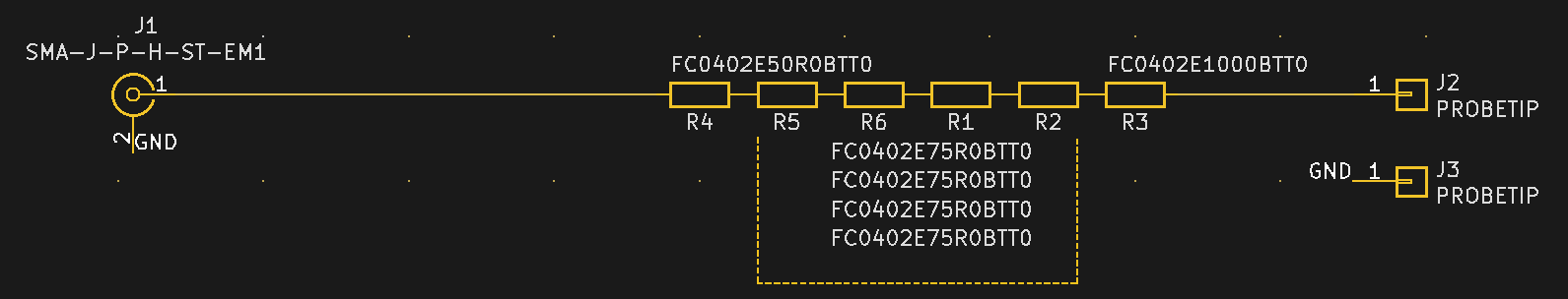
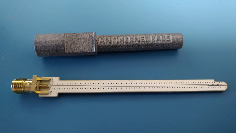
Don’t be fooled: the relatively simple schematic belies the complexity of such a design. At these speeds, the PCB layout is just as much of a component as the resistors themselves, and getting the transmission-line and especially the SMA footprint launch correct is no easy task. Using a combination of modeling with the Sonnet EM simulator and empirical testing, [Andrew] has ended up with a design that’s flat (+/- 1 dB) out to 1.98 GHz, with a 10-90% rise time of 161 ps. That’s a fast probe.
The probe comes in a few options, from fully assembled with traceable specs to a DIY solder-it-yourself version. You probably know which of these options you need.
We really like to see this kind of knowledge and thoroughness go into a project, and we’d love to see the Kickstarter project reach its goals, but perhaps the best part is that the design is permissively open-source licensed. This is a case where having the board layout open-sourced is key; the schematic tells you maybe half of what’s really going on in the circuit, and getting the PCB right yourself can be a long and frustrating exercise. So, have a look at the project, and if you haven’t got probes suitable for your fastest scopes, build one, or better yet, support the development of this exciting design.
We’ve seen [Andrew’s] oscilloscope work before, like glscopeclient, his remote oscilloscope utility program.


Nice design! Is the case in the photo ferrous or injection molded plastic?
Related: 1ghz active probe for $20 in parts, with a bunch of theory, as long as you have access to some good characterization and calibration equipment: https://www.instructables.com/id/DIY-1GHz-Active-Probe-for-Under-20/
1ghz passive probe with no PCB (so no issues with characterizing the pcb impedance): http://emcesd.com/1ghzprob.htm
I’ve built and tested the latter and it worked quite well. It also requires use of a signal analyzer to trim. I want to use a probe that has close to 2x the bandwidth of the scope it’s on, so the probe rolloff isn’t the limiting factor, and this did well.
Every scope company has such a probe, though 2ith higher bandwidth, typically 8-10GHz and with flatter response.
I recently published an article in Signal Integrity Journal about such probes.
The downside of several series resistors is that it increase non-linearity due to stray capacitance
Yes, better probes exist – but none even close to this price range. Of course stuff like the Picoconnect 900 series, LeCroy PP066, Tek 54006A, R&S RT-ZZ80 will do better, but those are all $1000+.
This probe is intended to compete with the likes of the Pico TA061, Keysight N2874A, etc for a fraction of the price. I’ve benchmarked it against the TA061, which I believe is the same OEM probe design as the N2874A, and got substantially flatter frequency response and close to 1 GHz more bandwidth. If you know of a <$600 commercial probe that outperforms my design I'd love to hear about it.
The prototype enclosure in that photo is 3D printed SLS nylon with 40% glass bead filler.
For various reasons I’m moving to a pure polymer shell with no glass infill on the final board.
Very cool. Have tinkered with HV probes a bit, using a balance of capacitance and resistance to attain reasonable frequency response. But pushing past 1 MHz was hard enough (HV probes are huge – 200 kV +…). Maybe a higher bandwidth one could be the next lock-down project.
Just an Idea.
If putting a resistor on the end of a piece of coax cable “sorta” works, then what about soldering a piece of resistance wire to the core of a piece of coax cable, then heating the core of the coax with a high current through the core and then pulling the resistance wire partially through the coax cable to replace the core.
Or with some calculation, use a metal tube and a piece of resistance wire, both of the correct diameter and make a coaxial arrangement from that.
Wire can be made very straight by putting one end in a vice, and the other end in a (accu) drill, and then pull on the wire and rotate the drill simultaneously to torque the wire.
I would not now it this works. My scope stops at 50MHz…
I think that most commonly available resistance wire, in gauges the same size as a coax core, would need to be several meters long to get the right resistance. By the time you’re into exotic alloys and special construction, you’re back to the $$$ a probe set problem again.