New Teensy 4.1 Arrives With 100 Mbps Ethernet, High-Speed USB, 8 MB Flash

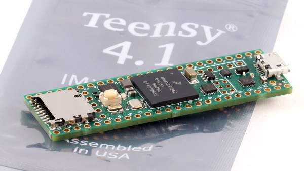
It was only last August that PJRC released Teensy 4.0. At that time, the 4.0 became the fastest microcontroller development board on the planet, a title it still holds as of this writing — or, well, not exactly. Today the Teensy 4.1 has been released, and using the same 600 MHz ARM Cortex M7 under the hood, is now also the fastest microcontroller board. What the 4.1 brings to the table is more peripherals, memory, and GPIOs. While Teensy 4.0 used the same small form factor as the 3.2, Teensy 4.1 uses the larger board size of the 3.5/3.6 to expose the extra goodies.

The now slightly older Teensy 4.0 — released on August 7th of last year — is priced at $19.95, with the new 4.1 version offered at $26.85. It seems that the 4.1 isn’t intended as a replacement for the 4.0, as they serve different segments of the market. If you’re looking for an ultra-fast affordable microcontroller board that lives up to its Teensy name, the 4.0 fits the bill. On the other hand, if you need the additional peripherals broken out and can afford the space of the larger board, the not-as-teensy-sized 4.1 is for you. How big is it? The sample board I measured was 61 x 18 mm (2.4 x 0. 7″), not counting the small protrusion of the micro-usb jack on one end.

Let’s have a look at all the fun stuff PJRC was able to pack into this space. Continue reading “New Teensy 4.1 Arrives With 100 Mbps Ethernet, High-Speed USB, 8 MB Flash”

Beautiful Free-Form LED Clock Recreates 20-Year-Old Weekend Project

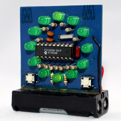
Here at Hackaday, we love a good clock project. And if it’s an artistically executed freeform sculpture, even better. But tell us that it’s also a new spin on a classic project from two decades ago, and we’re over the moon for it. Case in point: [Paul Gallagher’s] beautiful recreation of an LED clock riffing on one originally made as a weekend project in early 2000.

Wait, wait. Hold up.

*Ted unclips the microphone from his lapel and stands up from his chair*

OK, dear reader, if you’ll allow me, we’re going to do this one a little differently. Normally I’m supposed to write in the voice of Hackaday, but this project has personal meaning for me, so I’d like to break the rules a bit. You see, the original clock project was mine — one I did over a weekend a long time ago, as evidenced by the “2/13/2000” date on the PCB — and I was quite honored that [Paul] would choose my project as inspiration.

Original Clock Project dated 2/13/2000

When, on the 20th anniversary of creating this clock, I posted a Twitter thread to commemorate the event, [Paul] picked up the ball and ran with it. You can see the original Twitter thread here. Pictures of the home-etched single-sided board were all he needed to reverse-engineer the relatively simple design, and then re-create it with style.

The design uses a PIC16F84 microcontroller. This was one of the first microcontrollers to really become popular with hobbyists, the key features being the serial programming algorithm which allowed easy homebrew programmers, and the FLASH memory. If I recall correctly, my original programmer ran off a PC’s parallel port. I probably have it in a box somewhere. Each of the 12 LEDs is driven through a separate resistor from individual GPIO lines, while a 32.768 kHz crystal serves as the timebase. Finally, two buttons allow you to set the hours and minutes.

How do you represent three separate hands on such a display? In this case, each hand blinks at a different rate. The hour LED is solid, and the second LED blinks faster than the minute one. You can check it out in [Paul’s] video after the break, and admire the beautiful simplicity of his layout.

Since he was able to re-create the circuit exactly, [Paul] was able to drop-in the original assembly code that runs the clock. True-to-form, Microchip still manufactures the PIC16F84, and their latest tools have no problem with such legacy code — it just works.

Continue reading “Beautiful Free-Form LED Clock Recreates 20-Year-Old Weekend Project”

Open-Source 2 GHz Oscilloscope Probe

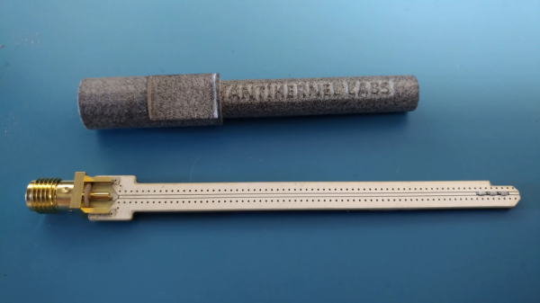
If you do any work with high-speed signals, you quickly realize that probing is an art unto itself. Just having a fast oscilloscope isn’t enough; you’ve got to have probes fast enough to handle the signals you want to see. In this realm, just any old probe won’t do: the input capacitance of the classic RC probe you so often see on low-bandwidth scopes starts to severely load down a circuit well below 1 GHz. That’s why we were really pleased to see [Andrew Zonenberg’s] new open-source design for a 2 GHz resistive probe hit Kickstarter.

The design of this new probe looks deceptively simple. Known as a Z0-probe, transmission-line probe, or resistive probe, the circuit works as a voltage divider, created from the 50-Ohm input impedance of a high-speed oscilloscope input and an external resistor, to reduce loading on the circuit-under-test. In this case, the input resistance has been chosen to be 500 Ohms, yielding a 10x probe. In theory, building such a probe is as simple as soldering a resistor to the end of a piece of coaxial cable. You can do exactly that, but in practice, optimizing a design is much more complex. As you can see in the schematic, just choosing a resistor of the right value doesn’t cut it at these frequencies. Even the tiny 0402-size resistors have parasitic capacitance and inductance that affect the response, and choosing a combination of parts that add to the correct resistance but reduce the overall capacitive loading makes a huge difference.

2 GHz Passive Probe Schematic

Don’t be fooled: the relatively simple schematic belies the complexity of such a design. At these speeds, the PCB layout is just as much of a component as the resistors themselves, and getting the transmission-line and especially the SMA footprint launch correct is no easy task. Using a combination of modeling with the Sonnet EM simulator and empirical testing, [Andrew] has ended up with a design that’s flat (+/- 1 dB) out to 1.98 GHz, with a 10-90% rise time of 161 ps. That’s a fast probe.

The probe comes in a few options, from fully assembled with traceable specs to a DIY solder-it-yourself version. You probably know which of these options you need.

We really like to see this kind of knowledge and thoroughness go into a project, and we’d love to see the Kickstarter project reach its goals, but perhaps the best part is that the design is permissively open-source licensed. This is a case where having the board layout open-sourced is key; the schematic tells you maybe half of what’s really going on in the circuit, and getting the PCB right yourself can be a long and frustrating exercise. So, have a look at the project, and if you haven’t got probes suitable for your fastest scopes, build one, or better yet, support the development of this exciting design.

We’ve seen [Andrew’s] oscilloscope work before, like glscopeclient, his remote oscilloscope utility program.

3D Metal Printer Uses Welding Wire

If you’ve seen both a fused filament fabrication (FFF) printer and a wire welder, you may have noticed that they work on a similar basic principle. Feedstock is supplied in filament form — aka wire — and melted to deposit on the work piece in order to build up either welds in the case of the welder, or 3D objects in the case of the printer. Of course, there are a number of difficulties that prevent you from simply substituting metal wire for your thermoplastic filament. But, it turns out these difficulties can be overcome with some serious effort. [Dominik Meffert] has done exactly this with his wire 3D printer project.

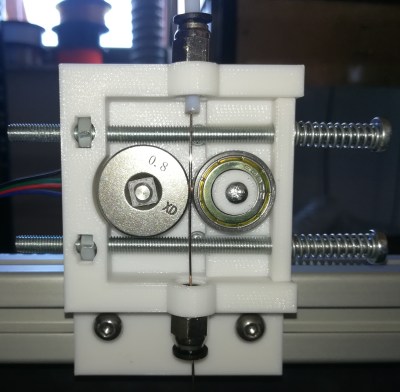
Extruder cold end using a standard feeder roller

For his filament, [Dominik] chose standard welding wire, and has also experimented with stainless steel and flux-cored wires. Initially, he used a normal toothed gear as the mechanism in the stepper-driven cold end of his Bowden-tube extrusion mechanism, but found a standard wire feeder wheel from a welder worked better. This pinch-drive feeds the wire through a Bowden tube to the hot end.

In thermoplastic 3D printers, the material is melted in a chamber inside the hotend, then extruded through a nozzle to be deposited. Instead of trying to duplicate this arrangement for the metal wire, [Dominik] used a modified microwave oven transformer (MOT) to generate the low-voltage/high-amperage required to heat the wire restively. The heating is controlled through a phase-fired rectifier power controller that modulates the power on the input of the transformer. Conveniently, this controller is connected to the cooling fan output of the 3D printer board, allowing any standard slicer software to generate g-code for the metal printer.

To allow the wire to heat and melt, there must be a complete circuit from the transformer secondary. A standard welding nozzle matching the wire diameter is used as the electrode on the hot end, while a metal build plate serves as the other electrode. As you can imagine, getting the build plate — and the first layer — right is quite tricky, even more so than with plastic printers. In this case, added complications involve the fact that the printed object must maintain good electrical continuity with the plate, must not end up solidly welded down, and the fact that the 1450 °C molten steel tends to warp the plate.

Considering all the issues that have to be solved to make this all work, we are very impressed with [Dominik’s] progress so far! Similar issues were solved years ago for the case of thermoplastic printers by a group of highly-motivated experimenters, and it’s great to see a similar thing starting to happen with metal printing, especially using simple, readily-available materials.

This isn’t the only approach to DIY metal printing, though. We saw one that used electron beam melting (EBM) not too long ago.

Thanks to [Krzysztof] for the tip!

Little Printer Dispenses Short Stories

We know how it happens. You buy a fancy new label printer, thinking this is the answer to your disorganized space, but soon entropy grabs the printer as well, and it becomes just another item in the pile. When you find such items later, though, they can spark ideas. The idea that struck [Eric Nichols] was to turn his diminutive thermal printer into a dedicated one for short stories.

Inspired by an article about a vending machine that dispenses stories selected by the reader’s time constraints, [Eric] took on the task of getting his Dymo LabelWriter 400 Turbo working in this new capacity. The first task was finding some continuous roll paper that would fit, because the official stock for this thing is all labels. He got lucky on the first try and a roll of 2 7/16″ receipt paper fit the bill perfectly.

The printer itself doesn’t have much brains; it prints bitmaps 672 bits wide, and as long as you care to make them. While the initial experiments succeeded in printing graphics, [Eric] needed a way to convert his stories to bitmapped text to send to the printer. The human-readable font file format known as BDF (glyph Bitmap Distribution Format) was a perfect fit, since a library to render it was readily available. On top of that, the open-source tool otf2bdf will convert a TrueType (TTF) font to BDF, completing his font-rendering chain.

[Eric] has these printers working with both Linux and windows, either one running on a PC where his software resides, and has it all well-documented on his site. With this in place, it’s simply a matter of coming up with the stories to print. We think it would be perfect for Hackaday dailies!

We’ve seen interesting hacks with disused printers before, like this ascii-art generating cartridge.

The Cult Of Really Low-Power Circuits: Scrounging, Sipping, And Seeing Power

If you’ve ever tried to make a really low-power circuit — especially one that runs on harvested power — you have probably fallen into at least a few of the many traps that await the unwary in this particular realm of electronic design. Well, Dave Young has been there, seen the traps, and lived to tell about it. In these territories, even “simple” systems can exhibit very complex, and sometimes downright confusing behavior when all possible operating conditions are considered. In his 2019 Hackaday Superconference talk: Scrounging, Sipping, and Seeing Power — Techniques For Planning, Implementing, And Verifying Off-Grid Power Systems, Dave discusses a number of these issues, how they interplay with low-power designs, and tricks he’s collected over the years to design and, more importantly, test these deceptively simple systems.

Dave is an electrical engineer and his company, Young Circuit Designs, has worked in the test and measurement, energy, and low-power consumer industries. We were lucky to have him share some of his 15 years of experience on the Supercon stage this past November, specifically discussing devices powered from harvested energy, be it wave energy (think oceans not RF), thermal energy, or solar. The first lesson is that in these systems, architecture is key. Digging deeper, Dave considers three aspects of the architecture, as mentioned in the talk title: scrounging, sipping, and seeing power.

Continue reading “The Cult Of Really Low-Power Circuits: Scrounging, Sipping, And Seeing Power”

The Truth Is In There: The Art Of Electronics, The X-Chapters

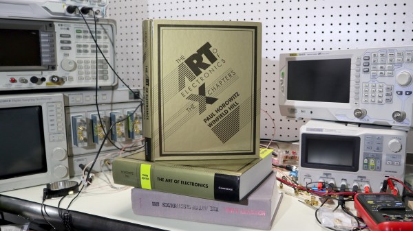
If you’ve been into electronics for any length of time, you’ve almost certainly run across the practical bible in the field, The Art of Electronics, commonly abbreviated AoE. Any fan of the book will certainly want to consider obtaining the latest release, The Art of Electronics: The x-Chapters, which follows the previous third edition of AoE from 2015. This new book features expanded coverage of topics from the previous editions, plus discussions of some interesting but rarely traveled areas of electrical engineering.

For those unfamiliar with it, AoE, first published in 1980, is an unusually useful hybrid of textbook and engineer’s reference, blending just enough theory with liberal doses of practical experience. With its lively tone and informal style, the book has enabled people from many backgrounds to design and implement electronic circuits.

After the initial book, the second edition (AoE2) was published in 1989, and the third (AoE3) in 2015, each one renewing and expanding coverage to keep up with the rapid pace of the field. I started with the second edition and it was very well worn when I purchased a copy of the third, an upgrade I would recommend to anyone still on the fence. While the second and third books looked a lot like the first, this new one is a bit different. It’s at the same time an expanded discussion of many of the topics covered in AoE3 and a self-contained reference manual on a variety of topics in electrical engineering.

I pre-ordered this book the same day I learned it was to be published, and it finally arrived this week. So, having had the book in hand — almost continuously — for a few days, I think I’ve got a decent idea of what it’s all about. Stick around for my take on the latest in this very interesting series of books.

Continue reading “The Truth Is In There: The Art Of Electronics, The X-Chapters”