At the heart of many amateur radio and other projects lies the VFO, or Variable Frequency Oscillator. Decades ago this would have been a free-running LC tuned circuit, then as technology advanced it was replaced by a digital phase-locked-loop frequency synthesiser and most recently a DDS, or Direct Digital Synthesis chip in which the waveform is produced directly by a DAC. The phase-locked loop (PLL) remains a popular choice due to ICs such as the Si5351 but is rarely constructed from individual chips as it once might have been. [fvfilippetti] has revisited this classic circuit by replacing some of its complexity with an Arduino (Spanish language, Google Translate link).
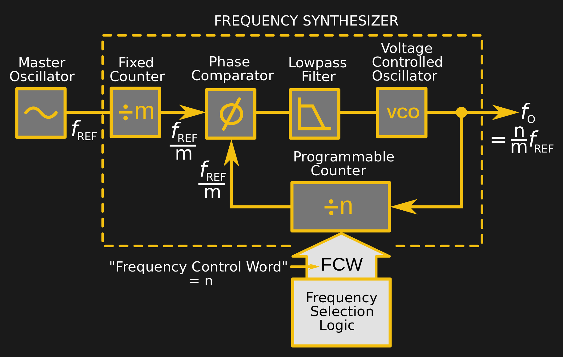
A PLL is a simple circuit in which one oscillator is locked to another by controlling it with a voltage derived from comparing the phase of the two. Combining a PLL with a set of frequency dividers creates a frequency synthesiser, in which a variable frequency oscillator can be locked to a single frequency crystal with the output frequency set by the division ratios. The classic PLL chip is the CMOS 4046 which would have been combined with a pile of logic chips to make a frequency synthesiser. The Arduino version uses the Arduino’s internal peripherals to take the place of crystal oscillator, dividers, and phase comparator, resulting in an extremely simple physical circuit of little more than an Arduino and a VCO for the 40 metre amateur band. The code can be found on GitLab, should you wish to try for yourself.
It would be interesting to see how good this synthesiser is at maintaining both a steady frequency and minimal phase noise. It’s tempting to think of such things as frequency synthesisers as a done deal, so it’s always welcome to see somebody bringing something new to them. Meanwhile if PLLs are new to you, we have just the introduction for you.


A chip which was designed to do this from the ground up is the Parallax Propeller — but alas, it doesn’t do it quite well enough since its internal PLL jitters, the signal contains birdies and harmonics which cannot be readily filtered out.
The Arduino and the Raspberry Pi were designed with set top boxes in mind.
Thy both have everything needed to control a tuner.
No jitter or harmonics.
The box is controlling a tuner.
Neither the Raspberry Pi nor the Arduino were designed with set top boxes in mind. Both may have been developed using CHIPS designed with set top boxes in mind, but that’s a whole different thing.
Propeller? Internal PLL? Tell me more about it.
I built a PLL for a 80m receiver around a 16F84 some 15 yers ago. The same processor handled the PLL, LCD and keyboard.
I love this. it’s getting back to the roots of low cost radio. I wonder what the drift is like.
The drift of a synthesized VFO depends solely on the stability of the crystal oscillator it uses as a reference.
Urm… why does he implement the PLL in the Arduino when he is already using the 4046 which is a complete PLL?
‘Corse he’s a sandwich or two short of a full Sunday school picnic.
“Complete” except for the dividers needed to get something other than a 1:1 frequency ratio.
OK, then one 74xx74 can be used as FLL allowing for any ratio.
..and then you need a user interface, which is easiest done with a microcontroller.
Ok. So what do you need to finish the project? 40 meter wavelength needs a pretty large(long) antenna right? Is this just a reciever then? Can it transmit (does it need an amplifier)?
This is just a variable-frequency oscillator, or VFO, which is a fundamental building block for both radio transmitters and receivers. You need all the other building blocks, which can include RF amplifiers, audio amplifiers, mixers, and intermediate frequency amplifiers and filters, for starters. Many transceivers (transmitter/receivers) are designed to use some of these blocks (including the VFO) for both transmitting and receiving.
The VFO is considered one of the most challenging parts in a transmitter or receiver, because it needs to be adjustable, but once adjusted, is expected to remain at the same frequency over a period of time and over a range of temperature, which are significant hurdles in their design. The wider the tuning range required, the more difficult it is to achieve high stability in simple oscillators. The phase-locked loop offers a relatively simple way of producing a variable yet stable oscillator.
Interesting and I would like to learn more.
However, I am not able to find code on the gitlab.
http://www.jodrellbank.manchester.ac.uk/people/staff/
All I see is the Readme.md file.
Perhaps I do not understand gitlab.
Forrest Erickson