An Atomic Pendulum Clock Accurate Enough For CERN

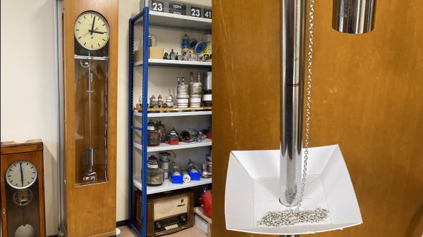
That big grandfather clock in the library might be an impressive piece of mechanical ingenuity, and an even better example of fine cabinetry, but we’d expect that the accuracy of a pendulum timepiece would be limited to a sizable fraction of a minute per day. Unless, of course, you work at CERN and built  “the most accurate pendulum clock on the planet.”

While we’re in no position to judge [Daniel Valuch]’s claim, we’re certainly inclined to believe him, mainly because the 1950s-era Czechoslovakian pendulum clock his project was based on, the Elektročas HH3, was built specifically as a master clock for labs, power plants, and broadcast use. The pendulum of this mid-century beauty is made of the alloy invar, selected for its exceptionally low coefficient of thermal expansion. This ensures the pendulum doesn’t change length with temperature, but it still only brings the clock into the 0.1 second/day range.

Clearly that’s not good enough for a clock at CERN, the European Laboratory for Nuclear Research, where [Daniel] works as an RF engineer. With access to a 10-MHz timebase from a cesium fountain atomic clock — no less a clock than the one that’s used to define the SI second, by the way — [Daniel] looked for ways to sync the clock up to it. Now, we know what you’re thinking — he must have used some kind of PLL to give an electromagnetic “kick” to the bob to trim the pendulum’s period. Good guess on the PLL, but the trimming method is a little cruder — [Daniel] uses a stepper motor attached to the clock’s frame to pay out or retract a length of fine chain into a cardboard dish attached to the pendulum’s rod. The change in mass changes the pendulum’s center of gravity, which changes its effective length, and allows the clock to be tuned a couple of seconds per day.

It seems like [Daniel] is claiming that his chain-corrected clock won’t drift more than a second from the cesium clock for 158 million years. Again, we’ll take his word for it, but it’s a wonderfully ad hoc approach to tuning the clock, and we appreciate its simplicity.

Finally, Tame The Si5351!

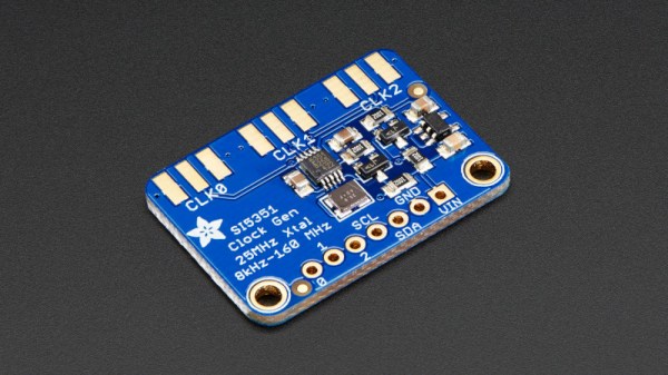
The Si5351 is an extremely useful device, containing multiple clock generators with many versatile programming options that go well beyond its original purpose of providing a clock for digital circuitry. It has in particular found a spot in RF projects, where it provides a cheap and effective stand-in for a variable frequency oscillator in everything from receivers to VNAs. It’s fair to say that programming the Si5351 isn’t the easiest of tasks though, and joining the various attempts to make this simpler is [MR-DOS], who has created an Si5351 library for the STM32 range of ARM Cortex M processors. Fortunately for those afflicted by the semiconductor shortage there’s the advice that porting it to other architectures should only require the relatively manageable task of modifying the i2c function for the new hardware.

Instead of being a full abstraction layer for frequency generation, this library provides functions to give access to the nuts-and-bolts of the chip such as PLL dividers. Thus there’s a need to understand the workings of a PLL and calculate its parameters, while in return much more flexibility over the chip’s operation can be had. We like this approach even though it requires a little more work from the developer.

Over the years this device has attracted a variety of libraries, this isn’t the first we’ve featured.

Header image: Adafruit Industries (CC BY-NC-SA 2.0)

Hacking A PIC To Redefine A Microphone’s Transmit Frequency

Software defined radio and widespread software-controlled PLL synthesis for RF has been a game changer. Things like the RTL-SDR can be any kind of radio you like on almost any frequency you like. But not every SDR or PLL system opens the configuration doors to you, the end user. That was the problem [vgnotepad] faced when trying to connect a Sennheiser wireless microphone to some receivers. They didn’t use the same frequencies, even though the transmitter was programmable. The solution to that is obvious — hack the transmitter!

The post is only part one of several parts and if you read to the end, you’ll learn a lot about what’s inside the device and how to crack it. Luckily, the device uses a PIC processor, so getting to the software wasn’t a big issue.

Continue reading “Hacking A PIC To Redefine A Microphone’s Transmit Frequency”

Run Your Favorite 8-bit Games On An ESP32

Here at Hackaday HQ we’re no strangers to vintage game emulation. New versions of old consoles and arcade cabinets frequently make excellent fodder for clever hacks to cram as much functionality as possible into tiny modern microcontrollers. We’ve covered [rossumur]’s hacks before, but the ESP_8-bit is a milestone in comprehensive capability. This time, he’s topped himself.

There isn’t much the ESP 8-bit won’t do. It can emulate three popular consoles, complete with ROM selection menus (with menu bloops). Don’t worry about building a controller, just connect any old (HID compliant) Bluetooth Classic keyboard or WiiMote you have at hand. Or if that doesn’t do it, a selection of IR devices ranging from joysticks from the Atari Flashback 4 to Apple TV remotes are compatible. Connect analog audio and composite video and the device is ready to go.

The system provides this impressive capability with an absolute minimum of components. Often a schematic is too complex to fit into a short post, but we’ll reproduce this one here to give you a sense for what we’re talking about. Come back when you’ve refreshed your Art of Electronics and have a complete understanding of the hardware at work. We never cease to be amazed at the amount of capability available in modern “hobbyist” components. With such a short BOM this thing can be put together by anyone with an ESP-32-anything.

There’s one more hack worth noting; the clever way [rossumur] gets full color NTSC composite video from a very busy microcontroller. They note that NTSC can be finicky and requires an extremely stable high speed reference clock as a foundation. [rossumur] discovered that the ESP-32 includes a PLL designed for audio work (the “APLL”) which conveniently supports fractional components, allowing it to be trimmed to within an inch of the desired frequency. The full description is included in the GitHub page for the project and includes detailed background of various efforts to get color NTSC video (including the names of a couple hackers you might recognize from these pages).

Continue reading “Run Your Favorite 8-bit Games On An ESP32”

An Arduino As A PLL

At the heart of many amateur radio and other projects lies the VFO, or Variable Frequency Oscillator. Decades ago this would have been a free-running LC tuned circuit, then as technology advanced it was replaced by a digital phase-locked-loop frequency synthesiser and most recently a DDS, or Direct Digital Synthesis chip in which the waveform is produced directly by a DAC. The phase-locked loop (PLL) remains a popular choice due to ICs such as the Si5351 but is rarely constructed from individual chips as it once might have been. [fvfilippetti] has revisited this classic circuit by replacing some of its complexity with an Arduino (Spanish language, Google Translate link).

The internals of a PLL frequency synthesiser
The internals of a PLL frequency synthesiser. Image by Chetvorno – CC0

A PLL is a simple circuit in which one oscillator is locked to another by controlling it with a voltage derived from comparing the phase of the two. Combining a PLL with a set of frequency dividers creates a frequency synthesiser, in which a variable frequency oscillator can be locked to a single frequency crystal with the output frequency set by the division ratios. The classic PLL chip is the CMOS 4046 which would have been combined with a pile of logic chips to make a frequency synthesiser. The Arduino version uses the Arduino’s internal peripherals to take the place of crystal oscillator, dividers, and phase comparator, resulting in an extremely simple physical circuit of little more than an Arduino and a VCO for the 40 metre amateur band. The code can be found on GitLab, should you wish to try for yourself.

It would be interesting to see how good this synthesiser is at maintaining both a steady frequency and minimal phase noise. It’s tempting to think of such things as frequency synthesisers as a done deal, so it’s always welcome to see somebody bringing something new to them. Meanwhile if PLLs are new to you, we have just the introduction for you.

Split Flap Clock Keeps Time Thanks To Custom Frequency Converter

Why would anyone put as much effort into resurrecting a 1970s split-flap clock as [mitxela] did when he built this custom PLL frequency converter? We’re not sure, but we do like the results.

The clock is a recreation of the prop from the classic 1993 film, Groundhog Day, rigged to play nothing but “I Got You Babe” using the usual sound boards and such. But the interesting part was getting the clock mechanism keeping decent time. Sourced from the US, the clock wanted 120 VAC at 60 Hz rather than the 240 VAC, 50 Hz UK standard. The voltage difference could be easily handled, but the frequency mismatch left the clock running unacceptably slow.

That’s when [mitxela] went all in and designed a custom circuit to convert the 50 Hz mains to 60 Hz. What’s more, he decided to lock his synthesized waveform to the supply current, to take advantage of the long-term frequency control power producers are known for. The write-up goes into great detail about the design of the phase-locked loop (PLL), which uses an ATtiny85 to monitor the rising edge of the mains supply and generate the PWM signal that results in six cycles out for every five cycles in. The result is that the clock keeps decent time now, and he learned a little something too.

If the name [mitxela] seems familiar, it’s probably because we’ve featured many of his awesome builds before. From ludicrous-scale soldering to a thermal printer Polaroid to a Morse-to-USB keyboard, he’s always got something cool going on.

Fail Of The Week: How Not To Design An RF Signal Generator

We usually reserve the honor of Fail of the Week for one of us – someone laboring at the bench who just couldn’t get it together, or perhaps someone who came perilously close to winning a Darwin Award. We generally don’t highlight commercial products in FotW, but in the case of this substandard RF signal generator, we’ll make an exception.

We suppose the fail-badge could be pinned on [electronupdate] for this one in a way; after all, he did shell out $200 for the RF Explorer signal generator, which touts coverage from 24 MHz to 6 GHz. But in true lemons-to-lemonade fashion, the video below he provides us with a thorough analysis of the unit’s performance and a teardown of the unit.

The first step is a look at the signal with a spectrum analyzer, which was not encouraging. Were the unit generating a pure sine wave as it should, we wouldn’t see the forest of spikes indicating harmonics across the band. The oscilloscope isn’t much better; the waveform is closer to a square wave than a sine. Under the hood, he found a PIC microcontroller and a MAX2870 frequency synthesizer, but a conspicuous absence of any RF filtering components, which explains how the output got so crusty. Granted, $200 is not a lot to spend compared to what a lab-grade signal generator with such a wide frequency range would cost. And sure, external filters could help. But for $200, it seems reasonable to expect at least some filtering.

We applaud [electronupdate] for taking one for the team here and providing some valuable tips on RF design dos and don’ts. We’re used to seeing him do teardowns of components, like this peek inside surface-mount inductors, but we like thoughtful reviews like this too.

Continue reading “Fail Of The Week: How Not To Design An RF Signal Generator”