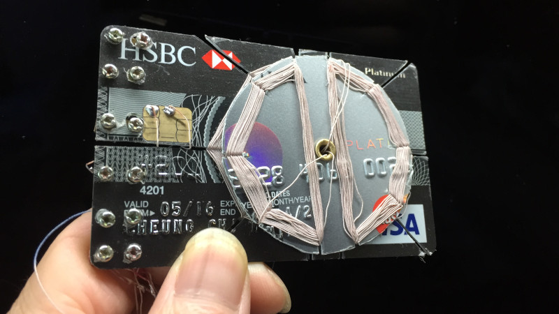
Perhaps the simplest radio one can build is the crystal radio. Using a diode as a detector, the design generally uses less than 10 components and no battery, getting its power to run from the radio signal itself. [Billy Cheung] decided to build a crystal radio using a rather unconventional detector – the smart chip in a common credit card.
This is possible because the smart chip on many credit cards contains a diode. It’s then a simple matter of hooking up the right pads on the credit card to the rest of a crystal radio circuit, and you’re all set. Of course, [Billy] goes the whole hog, building the entire radio on a single credit card. Other cards are cut up to create bobbins for winding coils to form a variable inductor, used to tune the radio. Doing this allows for a much cleaner, thinner design, rather than using a variable capacitor which is comparatively hard to find. Turning the dial allows stations to be tuned in, and with a high impedance earbud hooked up, you’re listening to AM radio. Oh, and don’t forget an antenna!
[Billy] breaks down the details for anyone wishing to replicate the feat, going so far as to wind the coils in real time in his Youtube video. Cutting templates and other details are available on Github. While it’s not going to be the most replicated hack, as it requires the destruction of a credit card to achieve, we love the ingenuity. And, if society does collapse, we’ll all have a great source of diodes when the ATMs have all become useless. Video after the break.
[Thanks to Zane Atkins for the tip!]


That’s cool. My dad was just asking the other day on building a Crystal Radio.
Much cooler hack would be to reprogram the smart chip to be actual (part of the) radio.
But it is part of the radio?
What?
I wonder if you can take it a step further and use the pickup coil in an RFID credit card as the tuning coil.
Probably nowhere near enough turns: https://hackaday.com/2014/08/23/disabling-tap-to-pay-debit-cards/
Typically they work on 13,56MHz afaik.
Downtuning would be possible by carefully adding a capacitor or perhaps sticking ferrite slices onto the card, but the 22m shortwave broadcast band ends at 13.57MHz so you wouldn’t receive much.
Probably nowhere near enough turns: https://hackaday.com/2014/08/23/disabling-tap-to-pay-debit-cards/
Back in the days, Germanium diodes are used for their low voltage drops. Chances are that OP is using ESD protection diode as rectifier which isn’t ideal as they have large drops. They also have high parasitic capacitance from the extra circuits attached.
Yes, I love salvaging germanium diodes from old audio gear. Great small signal performance
Yup. Here in Germany, Germanium diodes (OA95, OA91, OA89 etc) were quite popular in crystal radio sets / detector radios, for example. In fact, Germanium diodes are still available, but more pricey than silicon diodes.
Anway, a real old-school detector crystal is much better than any standard diode, quality wise.
You can check YT if you like. It’s amazing how well these old “rocks” actually perform in crystal radio sets. :)
I just measured a few smart cards, and I noticed most pads have 0.7V drop, but the top left pad (which is what OP is using. It’s the VCC pad) had 0.4V drop on all cards. I assume they put a reverse Schottky over the power rails to minimize negative voltage.
the trench radios used a piece of pencil lead and a rusty razor, guessing this is better :P
I tried the razor detector myself – it works, but it is more a novelty than a serious receiver.
If you were a bored american stationed in Germany, where the US army had or has several American Forces Network transmitters, you could easily pick them up on base.
However, my ears perceive the signal as a good 20-30dB quieter than a germanium diode detector.
AFN was also kinda popular among German citizens in the 1990s, I recall. If memory serves, in my place it was on-air on 1,6MHz or so (upper end of the medium wave band).. Anyway, I’m speaking under correction. I was very little when the US army people left our place in 1995 or so.
I still remember the farewell party and the fireworks..
That’s true.
There was once an article that used the input only of a 709 opamp, it providing the right clamping diodes for the project. But the needed clamping voltage was much higher. This was the seventies, 709s were already cheap.
ESD diodes have a voltage drop under microamperes of like 0.2V which is respectable compared to germanium diodes (they’re schottky). Capacitance and the shape of the V-I curve is a little less ideal, but they’re great for crystal radios nonetheless.
I’m wondering how I managed to avoid noticing that style of coil tuning before. Aside from variable slug types for trimming. Gives me ideas about making tuners from old floppy drive pancake motors. Though with too many lobes to the coil I guess you get a narrow angle of tuning range.
Now you’ve given me an idea of building one of these into a floppy diskette!
Could you create wireless/battery less earbuds using this technique? Assuming you can get your phone to emit the correct radio frequency? You’d need to be at a tight frequency and for some sort of filtering or analog encryption to prevent stray signals from coming on.
The antenna’s going to be a lot longer than the headphone lead would have been.
I guess we should all give him some ‘credit’
I am really honored that my creation gets into this online magazine. Besides creating radios in credit cards, I had also credited retro Game machines – Arduboy clones and aTTiny on credit cards. Billy Cheung.