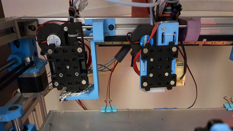
One of the Holy Grails of desktop 3D printing is the ability to print in multiple materials, for prints that mix colours or textures. There are printers with multi-way hot ends, add-ons that change your filament, or printers with tool changers, that swap hot ends as needed. [Amy] has taken the final route with her Hypercube, and her Doot Changer allows her to print in two materials with ease. Best of all, she tells us it only cost her $20 to make.
For those not familiar with Hypercube-style printers, they have a roughly cubic frame made using aluminium extrusion. On the rear upper rail are a couple of receptacles with metal locating pins onto which a hot-end unit can be slotted. The printer carriage has a magnetic coupling that can pick up or disengage a hot end from its receptacle at will, as can be seen in action in a short video clip.
All the parts can be found on Thingiverse, and there is a photo album with plenty of eye-candy should you wish to see more. Meanwhile as far as tool changers go, we’ve been there before in great depth.


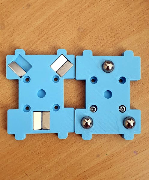
Does the video clip have a 4 point coupling? Not the kinematic (Maxwell) coupling in the photo? The kinematic with magnets is very cool.
No, what you can see is the rear facing edge of the “Doot Changer”. The part that isn’t visible has the three magnets.
Yeah, I’m not seeing it. I’m seeing the parts in the closeup as black parts in the video and with 4 metallic disks that could be magnets. No balls and no constraints. I’m missing something, but I like what I see.
Looks like two revisions to me. First one being the 4 magnet? on a plane version next one using balls and V grooves..
As 3d prints have very little lateral force on the head I expect its fine.. But I do wonder if it really does stay consistently located – Higher speed printing so its own mass and the hot-end’s umbilical acting against the magnets seems like it could be a serious problem for accuracy.
it’s not a new system, it works, https://hackaday.com/2017/08/27/3d-printer-tool-changer-gives-you-access-to-lots-of-extruders/
Not saying it won’t – but the system you linked to has some serious registration pins that will make any movement of the hotend in the holder rather hard and other versions I’ve seen use rotating cams to lock the heads in – this is just magnetic with it seems no mechanical assistance which is where my worry comes in.
Thicker stiffer filaments, high print speeds or rapid moves between areas this layer you are looking at a lot of force on the hotend with it seems nothing holding keeping it tight against the registration balls but the magnet – and magnets both age, and are not hard to slide apart – heck this system relies on being able to slide to them apart so limiting the maximum strength of the magnet too (crank it up too high lowering the risk of it shifting in use and something on the machine will stretch or fail rapidly at tool changes- assuming the steppers have the torque to pull against that loading – the sweet spot if there is one at all seems rather narrow).
Tested mine at 5000 Accel to 10k Accel and it stayed locked just fine :)
Magnets can be very strong !!
Oh and the first revision uses a 3d printed coupling that suffered from wear.
It’s the same color as the rest so it’s hard to see :)
Hello! I’m the one who made the printer
The early version had 4 magnets that are ever so slightly away from each other so they don’t touch and act as only a pulling force. The idea of the first version was to use the plastic’s bending and wear to my advantage but it only worked well for 1-2. Months.
The second version has a metal coupling and the coupling as magnets so you don’t need to worry about touching magnets/distance! Has been working great do far but this version needs a middle ring magnet for direct drive/heavy fools. But that’s honestly not a big deal at all. Just an extra 1-2$ at most for those tools.
For the record- 3 point spherical face couplings very similar to this are exactly what the roughly $500,000 Hexagon Metrology CMM (coordinate measuring machine) I use to measure my dies at work uses for interchangeable probe tip couplings. The machine uses 3 tiny carbide spheres at 120 degrees on the top face of the probe tip, with a strong neodymium magnet in the middle epoxied or friction fit into the aluminium probe body.
The main CMM head has 3 hemispherical carbide anvils, like a little halfpipe, that orient and seat against the spheres, and another magnet attracts the one ib the probe body. There is a 4th carbide sphere at an odd angle that goes into an orientation slot, so the probe always goes on the same axial orientation for calibration, but its basically a 3 point hard contact surface, and the magnet that attracts is in the middle. 3 points are minimal to define a plane in space of course- so it goes to the exact same spot every time. Can’t find a vid on youtube of it, apparently its too high end…
Really cool to see that principal applied to interchangeable toolheads in a similar way on a 3d printer.
Are you describing the interface used by Renishaw on the TP200 probes? https://www.mscdirect.com/product/details/00551275 for a picture.
Renishaw invented the 6-ball / 3-rod kinematice probe, so it’s no real surprise that they use a similar design anywhere they can.
Our Zeiss CMM uses the 6 rod/3 ball location method and that is easy to replicate with 3D printed parts. 6 dowel pins glued into slots and 3 loose bearings glued into holes on the mating part makes for very repeatable locating. Magnets in each for firm holding, or as others have done use a rotating wedge lock. One other tidbit, our CMM uses a coil (electro magnet) to cancel out most of the magnet force on release.
Love the implementation. How is this managed in software via CAD or Gcode? Is there a way to automate this, i.e., print this layer white and this one black? Doing this manually would not be ideal.