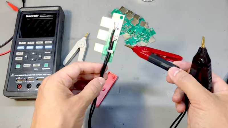
[VoltLog] has a cheap Hantek LCR meter, but it only has two probes. The best resistance and impedance measurements, though, use four wires to improve accuracy. The first order of business was a custom PCB to fit into the connector of the meter, along with a 3D-printed case.
Using a four-wire scheme requires unusual alligator clips that don’t electrical short the jaws together. The clips were hard to solder and even harder to strain relief. but [VoltLog] seemed to handle it with little problem.
There are some ready-made solutions for this, of course, but the good ones aren’t cheap. Besides, this way, the lead length is exactly what you want and you can control the entire construction, including sheilding and strain releif.
If you haven’t run into four-wire sensing before, it is a simple idea. In a normal two-wire measurement, you send a voltage through the device under test and measure the current through the wires. But since you’re using the same pair of wires to deliver the current and measure it, the resistance of the test leads get tangled up in the measurement.
With four wires, one pair of wires is used to supply the current, and the other to measure the voltage drop across them. The sense wires won’t carry very much current and, thus, there won’t be a significant voltage drop between the device under test and the measurment device. There may be a drop across the supply wires, but we don’t care anymore.
We have seen four-wire measurements in a lot of different places. We even simulated how it improves measurements and you can too.


“you send a voltage through the device under test and measure the current through the wires”
Huh? Wha?
Shoot a voltage through the device?
I know what you are trying to say, here, but… no
Also, most DVMs (might be all at this point), and many electronic analog meters going back to the 1960’s, have constant current source for the resistance scale and measure the potential develped, 2-wire and 4-wire. No reciprocal math needed, and current sources are cheap and easy.
LCR bridges to this the opposite way: force voltage, sense voltage and current. Components like capacitors are tested at specified DC and AC bias levels, so it makes sense to use voltage excitation and spare the user from doing all the conversions.
You are correct, Cliff. I am sure Al knows what he meant, but I think precise language is more likely to bring correct understanding, so things like this bother me too.
I am not a meter designer, but I am an engineer, and if I were designing a 2 wire digital ohmmeter, I would definitely use a regulated current source and measure the voltage drop. That would be much easier than trying to build a regulated voltage source and measuring the current. Especially since the normal way of measuring current in a digital circuit is to use a series resistor and measure the voltage drop. Plus you can more simply compensate for lead resistance in a constant current circuit because it’s just an offset to subtract. In a constant voltage circuit the lead resistance is in the denominator of the current measurement which means you have to adjust gain somewhere or do math after the conversion to digital.
This PCB adapter is very intereseting. Where I can buy this PCB? I’m from canada