When working with hardware, whether a repair or a fresh build, it’s often necessary to test something. Depending on what you’re working with, this can be easy or a total pain if you can’t get the right signal to the right place. To eliminate this frustrating problem, [WilkoL] built a useful pulse generator for use in the lab.
[WilkoL] notes that historically, the job of generating pulses of varying length and frequency would be achieved with a smattering of 555 timers. While this is a perfectly cromulent way to do so, it was desired to take a different approach for the added flexibility modern hardware can offer. The pulse generator is instead built around an STM8 microcontroller; an unusual choice in this era, to be sure. [WilkoL] specified the part for its incredibly low cost, and highly capable timer hardware – perfect for the job.
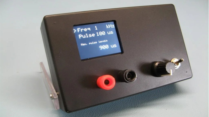
Combined with an ST7735 TFT LCD screen, and programmed in bare metal for efficiency’s sake, the final project is installed in a project box with controls for frequency and pulse length – no more, no less. Capable of pulse lengths from 250 ns to 90 s, and frequencies from 10 mHz to 2 MHz, it’s a tool that should be comfortable testing everything from servos to mechanical counters.
Of course, if you need to get down to picosecond timescales, an avalanche pulse generator might be more your speed. Video after the break.


But what about the output impedance, offset and amplitude ?
It is a toy “lab” tool like many DIY projects shown here. Or rather a tool for a very specific task (in this case with those parameters fixed), much more specific than generic (and indeed more expensive) lab equipment.
Covered in the actual write-up. Output impedance is fifty-something ohms (3 outputs of a 74HC14, each with a 150 ohm series resistor, are paralleled). Output levels are fixed at 0 and 3.3 V.
The output impedance of a port-pin on a microcontroller is usually on the order of 30-50 ohms. A small series-resistor (22 or 27 ohms for example) will bring it nicely into the 50 Ohm range. Not accurate, but often close enough.
From an LSI chip, I expect way less powerful drivers. More like 150 ohms. So significant compared to the intentional 150 series resistance.
I really like the bare metal approach. Very useful for who wants to learn with STM8 hardware from scratch by just starting to look at the code, without delving into standard libraries.
I always use the bare metal approach for STM32. The biggest disadvantage is a lack of support. If you get stuck, then you’re on your own.
Most of the time, the reference manual has much better explanations of how things works than trying to figure out from library. I code in bare metal too as it’ll take me longer to figure out the correct parameters to pass to a library than just read off the reference manual.
For the rare moments when there are error handling or specific initialization sequence, it would be worth while to see what the library does. You can cheat and use SWD hardware debugger to see the before/after calling the library effect on the peripheral registers. You can also use a source code debugger to trace the library code logic. It is far easier than to understand code with nested #ifdef #else statements.
First up disclaimer – I’m referring to my work here.
You can find out more on the STM8 through a series of articles I put together a while ago, check out The Way of the Register series of posts: https://blog.mark-stevens.co.uk/the-way-of-the-register/
And those articles were (are) much appreciated. I read most of them, together with those on Embedded Lab. Thanks.
What is the rise time? It should be easy to glue a cheap TDR head onto it to steepen the rise time?
You should be able to replace the 74HC14 that is used as a driver with faster parts. e.g. 74AC14
There might be even faster parts with the newer families too.
FYI: http://www.interfacebus.com/IC_Output_Slew_Rate.html
How about a one-shot option? You’d be surprised how often that need arises.
It gets more tricky as it would involve interrupt latency + latency for the code to set up an output compare.
Some of that can be reduced by adding a flip-flop to handle the trigger and the output compare to reset..
You had me with “cromulemt”.
🤣
“Cromulent” … dang iPad keyboard!
I tried an STM8S and think they’re great little chips. They really deserve a lot more love in the maker community.