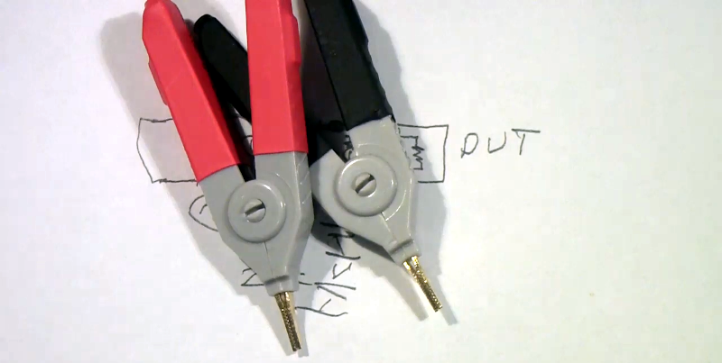
You might think the probes in the picture are just funny looking alligator clips. But if you watch [tomtektest’s] recent video, you’ll learn they are really Kelvin probes. Kelvin probes are a special type of probe for making accurate resistance measurements using four wires and, in fact, the probe’s jaws are electrically isolated from each other.
We liked [Tom’s] advice from his old instructor: you aren’t really ever measuring a resistance. You are measuring a voltage and a current. With a four-wire measurement, one pair of wires carries current to the device under test and the other pair of wires measure the voltage drop.
If you wonder why that’s better than two probes, it all comes down to resistance in the test probes. Pulling supply current through the probe wires — which have some resistance — causes a voltage drop that affects the measurement. While the sense wire pair will also have resistance, the sensing current can be very small which means there will be correspondingly less error in the measurement.
We’ve seen these probes built from scratch, too. You do need a meter that will do the actual four-wire measurement, although a power supply and a voltmeter will do the job, too. If you don’t want to probe in real life, you can always do it in virtual reality. (Well, a circuit simulator, anyway.)


a very instructive video. thanks
Really? As if 4-wire/Kelvin measurement was anything new and exciting… Must be a really slow day.
You do realize not everyone that reads the site is actually extremely knowledgeable with electronics, correct?
Plenty of people probably don’t know about it. Like there’s always a beginner somewhere.
I myself suck with electrical stuff but I have heard of this before so actually seeing an article that’s an overview of it this helpful to me.
For those of us not born with the level of knowledge you were, let us learn. Thanks for the article, Al.
I knew what Kelvin sensing, but I always assumed you just used four different clips. I never actually had a reason to do it myself though.
The DER lcr meter he uses is an extremely good buy for an accurate and wide-range unit. Inexpensive as far as semi-lab-grade meters go. What he doesn’t mention is that a Kelvin configuration is probably not necessary for hobbyist use. If the resistance/impedance of the test leads are significant relative to your part and your desired accuracy, sure. If you need an accurate measurement of a tenth-ohm brushless motor winding, yes you need it since your test leads have a significant resistance compared to a tenth of an ohm. If you’re measuring a 1K resistor to 1% accuracy then a Kelvin configuration would only be necessary if your test leads are more than 10 Ohms. Unlikely. Measuring to 0.1%, Kelvin would be necessary. Any LCR meter is better than no LCR meter. For resistors, you can generally get 1% or even 0.1% resistors pretty cheap. That’s definitely not true when it comes to caps and inductors. 5%, 10%, 20% or more are common tolerances. If that’s important for your design then you probably need an LCR meter. Once you have a meter then you can worry about whether Kelvin probes are necessary or compatible with your meter
Usually the need for Kelvin probes is solved by sticking the leads together and subtracting the result from your measurement. For a common multimeter, the resistance of the leads is too small to show up on the meter, or it is already subtracted when the meter was calibrated.
This may be good enough, or it may not be. In particular, when the contact resistance can be significant, this does not work and a four wire approach is needed.
A case I see on occasion in the lab is measuring the resistance of a heater wire, where the alloy grows an oxide film. Even at several ohms, it may be impractical to measure the resistance using a two wire method without damaging the wire.
The century old four electrode arrangement is quite common during the geoelectric measurements in geophysics. It is absulutely necessary in those cases because of high level distortions caused by hectic transition resistances at the ground electrodes, greatly depending for example from the humidity of the soil (and from many other factors too). In case of VES (Vertical Electrical Sounding) measurements, a pecisely regulated current is supplied through a pair of source electrodes (A, B) and the voltage is measured between receiver electrodes (M, N). The penetration depth of source current into the ground is changing in (not a linear) dependence of A-B distance. From the measured M-N voltage, an aproximate conductivity distribution can be calculated in function of depth, beneath the M-N location. ( See wiki page provided by Society of Exploration Geophysicists (SEG) for more details: https://wiki.seg.org/wiki/Electric_resistivity_methods )
I have seen plenty of people wire up kelvin probes incorrectly through the years…
And this video mostly goes through the theoretical side of things.
But the idea behind the 4 wire measurement is that one can remove the effects of contact resistance. (And also thermal effects if one’s connections are close enough to each other to have “about the same” temperature.)
But I have seen a lot of people take a “Kelvin probe” and then connect both wires to the same side of the connector…
Ie, one has the sense wires connected to the source/ground in the connector, not in the device under test.
The Kelvin probe isn’t just a “fancy” alligator clip, but the two jaws of it are actually electrically isolated.
This means that our sense wires and our source/ground wires all have their own contact resistance. And this is what we want.
Since the source/ground wires are low impedance wires where all we care about is current. So any voltage drops over the contact resistance is largely irrelevant.
And our sense wires only cares about voltage, and have an excessively high impedance, meaning that the contact resistance that usually is bellow an ohm is not sufficient to effect even the last significant digit on most meters supporting 4 wire measurements.
The only thing left to toss a wrench into our measurement is thermal EMF…
But some wise material choices and keeping any temperature gradients as small as possible is usually a decent enough solution. And here is why the Kelvin probe has the upper hand compared to just using four alligator clips, the Kelvin probe has its two contact points much closer to each other than what we could reasonably get with alligator clips or other test hooks. This means that any thermal gradients will inherently be smaller through that alone.
Though, for most measurements, just having 4 contact points can improve measurement accuracy rather substantially.
And even if one wires it up incorrectly, at least one has nulled out most of the wire resistance in one’s test leads…. (Though, an incorrectly wired Kelvin probe is usually worse than 4 independent alligator clips or other test hooks…)
I understand that two wire method is succeptible to probe cable adding to the measured resistance, but couldn’t you just calibrate device to compensate for that? (given that temperature of the cable is constant and measurement current is low enough not to heat the cable significantly)
4 wire measurements isn’t just about nulling out the cable resistance.
But also the contact resistance. That varies with each successive connection, due to variations in contact area and deformation of the base material. (in short, variations in contact pressure.)
And any thermal induced voltages/currents. That varies depending on thermal gradients.
Secondly, when measuring sufficiently small values, the wires in a 2 wire setup will add a significant offset to one’s measurement. So it does eat into the resolution of the measurement, since additional resolution will be needed to also include the offset in one’s measurement.