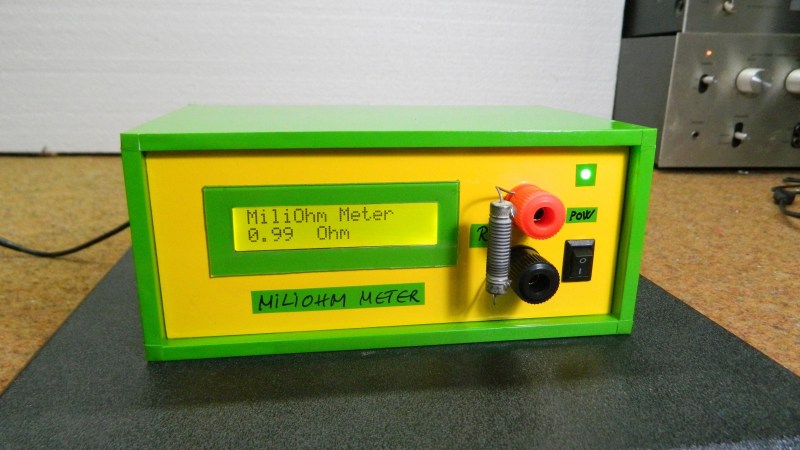
User [mircemk] presents his “MiliOhm Meter” project which you can build with an Arduino, a handful of common parts from your lab, and a cigar box. It doesn’t get much simpler than this, folks. While this is something you won’t be getting calibrated with NIST traceability, it looks like a fun and quick project that’s more than suited for hobbyist measurements. It’s not only easy to build, the Arduino sketch is less than thirty lines of code. This is a great learning project, plus you get something useful for your lab when its finished.
We like the creative use of colored tape instead of paint on the project’s box. If this style suits you, [mircemk] has published several other similar lab instrument projects on his Hackaday.io page, including a frequency meter, an audio spectrum analyzer, and an auto-ranging capacitance meter to name a few. You might recognize him from some other projects we’ve featured, such as the crazy kinematic arms that set a clock’s hands every minute.


It’s not one.
It’s a “miliohm” meter according to the label. Perhaps “miliohms” are equal to 10 correctly-spelled milliohms?
A 4-wire method would work much better for just a few extra parts.
I was also a bit horrified when I saw the schematic (plus a lousy ADC and no temp comp). But that is the case with so many Arduino-named projects that I usually just skip past them.
For a high current measurements like this you get indeed relatively big deviations with only a 2 wire measurement.
On top of that, the low voltage over the shunt itself is still poorly matched to the ADC of your uC.
If you go to all the trouble of writing the code and making the box and power supply etc, then adding an opamp with a bit of amplification would have been a small extra step.
But instead of this I would prefer to simplify the circuit, which is also much more accurate.
Just use a LM317 and a resistor to turn it in a calibrated current source / sink of 100mA (or also make a 1A version), and then use a regular power supply and DMM to make measurements.
Without a true 4-terminal measurement your mΩ meter is really measuring the contact resistance between probe and sample. Not very useful.
As an electrical engineer, I too initially cringed at the measurement circuit and the two-wire probe. But despite that, I like this family of projects. Clearly they fill a need in his lab, and the simple construction means he can improve them as necessary over time. I say cut him some slack, although I would like to know the origin of the project’s unusual spelling.
Maybe it’s a subtle nod to it not being as precise as a 4 wire device with better accuracy.
Hmm, indeed a nicely simple circuit, might be easy to add temperature compensation and make it 4 wire without drama.
Thanks for post
Nice project! I did something similar but more complex by making a capacitor ESR meter that can also measure resistors in the milliohms range. Another one with voltage regulator configured as current source, and a DVM. For ballpark measurements it’s ok.
This project can be improved by using the brownout band gap voltage reference and the temperature sensor in the atmega328P microcontroller.
Aside from that, taking multiple measurements and averaging them helps keeping noise under control. This mcu can also sample the ADC in sleep mode to reduce noise even further. This may need you to look into the datasheet and configure the ADC manually.
Also, a zeroing feature can help nulling the resistance in leads and connectors by shorting the input and a button that activates the zeroing feature. Remove the short and place the DUD.
I had a hard time getting good measurements out of an Arduino. Connect a LM4040 to the AREF pin and use the “analogReference(EXTERNAL);” command. I used a 4.098v chip so “const float VOLTS_PER_UNIT = 4.098 / 1023;” did the job.
It’s sufficient.
Contact resistance can very easily be tared out if you really require (very doubtful) better accuracy than you get by just using it “out of the box”, as can test lead resistance. Sure, it’d be better if you made it an analog meter based on a microammeter, but – I know, a lot of today’s sparky kids don’t know how to read analog displays. 8)