One of the problems with using a Raspberry Pi or most other systems in a production environment is dealing with sudden shutdowns due to power loss. Modern operating systems often keep data in memory that should be on disk, and a sudden power cycle can create problems. One answer is an uninterruptible power supply, but maintaining batteries is no fun. [Scott] wanted to do better, so he built a UPS using supercapacitors.
A supercapacitor UPS is nearly ideal. The caps charge quickly and don’t wear out as a battery does. The capacitors also don’t care if they stay in storage for a long time. The only real downside is they don’t have the capacity that batteries can have, but for a small computer like a Pi Zero it is pretty easy to gang up enough capacitors to do the job.
In particular, [Scott’s] design uses five 10F capacitors, each charged to 2.5V. The downside is that this requires a 12V supply, so he did a second design that uses only two capacitors each taking half of a 5V supply.
There are several options for converting the capacitor voltage to the desired output voltage. There’s also software to run the onboard microcontroller and force a shutdown in the Pi if the main power drops.
Naturally, this isn’t an original idea, but it is well done. You can also buy cheap ready-made UPS boards in the Pi form factor, but you might want to check out some aftermarket software for them if you use one.


“In particular, [Scott’s] design uses five 10F capacitors, each charged to 2.5V. The downside is that this requires a 12V supply, so he did a second design that uses only two capacitors each taking half of a 5V supply.”
This is the most interesting of the design decisions, but these sentences provide nearly zero info.
How long did it run on 50F@2.5V?
How long does it run on 20F@2.5V?
Why reduce energy storage by 3/5ths?
What’s the power topology and how efficient is it from caps=>RPi?
How did that change between v1 & v2?
What specific DC/DC was chosen and how was it optimized?
How does the MCU interface with the RPi?
I don’t ever want to watch a youtube video – so much time for so little info. I can read much faster than people speak and especially can process data faster in a table than verbally – I think this is the same for most humans (especially those on this site).
Now that I think about the sentences more – you mean because they didn’t want to use a 12V input (which perhaps went straight to a serial arrangement of super caps… for some reason???), they use a 5V input onto 2 caps….
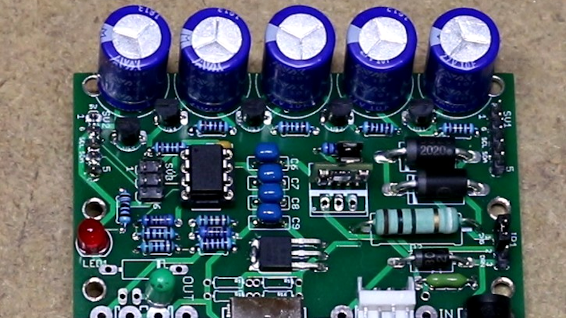
I think I see an inductor in the bottom center of the title pic. I sure hope that’s used to DC/DC the caps to a 5V rail, rather than running the Pi off the caps V+ directly…. It would be a tremendous waste of the stored energy otherwise. It would be really nice to know this by reading the article :)
These are the interesting details of this build, and I think the majority of the audience would appreciate it if you would expound upon the specifics in the text, given that you watched the video. It wouldn’t take much longer to aggregate this for us if you watched the video and spent the time to write an article. That said please don’t take this too negatively!! Definitely an interesting project, and I appreciate the fact that you spend time to write about these things, amongst many other ways to make money.
Cheers y’all (especially Al & the board designer)! Keep hackin!
(yeah, I know it may have taken longer to write this than to watch the vid – my hope is that somehow this will push the trend towards having a bit more details in the text, but ay, I get it’s unlikely to happen)
+99
As interesting as it is, some basic analysis from a hackers perspective would be great. Why not take it further & ask the author directly & give a hacking journalistic aspect to the post.
I didn’t make it to the end of ha comment. How about you out it in the dorm of a table?
Tables are going to college these days?
ftfy:
>HaD article is lacking detail
>”I don’t like videos” (agreed)
>Please aggregate technical details from projects and place in future articles
>Thanks for the hard work everyone
:P
Separately, why do people still do through hole? So much more work and often more challenging than SMT
Through hole makes for easy prototype -> final product transition, the parts are easier to work with and you can do it all with one soldering iron (no hot air, no solder masks, no microscopes).
SMT is nice if you have a physical space constraint or you are going to produce in volume.
This. SMT can be awesome for complex circuits where there are size and routing constraints, but it requires more specialized equipment that takes a lot more space and can get pretty expensive. Through hole, you can do with just your hands and a half decent soldering iron, very cheaply, and in extremely limited space. It also tends be easier to maintain, because you can’t always just take out the board and throw it in a reflow machine, and in many settings, you just won’t have the stability, lighting, and physical access to position and hand solder SMT components. I love using pre-fabricated SMT devices and dev boards, but I just don’t have the means to work with SMT right now, so through hole is really good for me. If you are lucky enough to be in a position where you can afford to avoid through hole, that’s awesome, but a lot of people don’t have that.
I personally prefer through hole. It’s much easier and less challenging when you don’t have specialized equipment or room for such equipment. It’s also many times easier to do field repairs, when you can’t necessary pull out the entire board to put in a reflow machine every time you need to replace a component.
I only wish I had such a budget that I could afford to complain about through hole being harder than SMT. For me, through hole is far far easier and less challenging
Feel like its worth pointing out the first link in the article is to a nice wordy explanation of what is going on, and what thinking there is behind it.
So you can have a good read of the creators reasoning if that is your preference (which it is for me as well – video’s are all well and good, but usually full of wasted of time)
>”video’s are all well and good, but usually full of wasted of time”
I couldn’t agree more! Videos are very useful for mechanical aspects, such as disassembly/assembly. But for knowledge-based information, a horrible waste of time IMHO. Autodesk, to my dismay, seems to believe all of their product support should be done in a video format. Something needing a few sentences takes minutes to walk through… :(
The best part of Youtube is the button that lets you speed it up. I find almost all videos can be intelligible at 1.5x.
I’m seeing more and more comments from people that despise videos. I have the same view.
Is it *really* too much to ask for the writer to watch the video himself/herself and write the article as a summary?
HaD is becoming a site of “There is this cool gadget, but I can’t be bothered to tell you what it is, so here is a link to a [waste your time] video”
Sort of this.
I find out weird that so many cool projects are reduced to a YT video and a summary without substance.
I guess a lot of people read these articles during short pauses, without headphones or other means to listen.
He says up to a minute with the 12V version (look at 14:50 in the video) and less than 30 seconds with 5V (look at 21:40).
3 minutes or 30 seconds? Urg. You do realize you can get a UPS that gives you 120VAC for about $40. It is silly and wasteful to go up and down like that but I also suspect you get more runtime even at the reduced efficiency. Also a 120V UPS is handy for other things like keeping the rest of your networking gear up, or even running an LED lamp. In fact a friend of mine has a few UPS’s that just power LED lamps. If the power goes out he has to start his generator up and replug a couple of things, but the house lights stay on so he can see what he is doing.
Nice. People get on here whining that they didn’t get enough free labor from the author already and want more because they are too lazy to watch the video. Did you even look at how much you typed? You could have watched half of the video in the time it took you to do that. My brother watches YouTube videos at double speed when he wants information, and had you done that, you could have gotten 100% of the information the author had, in around the same amount of time it took you to whine that he (or she…) didn’t do enough free labor for your fricking royal highness.
Now excuse me, I’m going to watch the video, because I actually care enough about this enough to put a bit of my own time and effort into learning about it.
Great!
Put a normal lipo AND supercapacity and put on tindie
I need this.
All of them use only one power storage source. And I would like different ones, e.g. 2 different battery capacities (and different consumption) and supercapacitors in one device.
What would be the benefit of having multiple types of storage?
Don’t see much use for alternate storage types either. Power over Ethernet supplied UPS becomes different.
Same question? Why a battery and caps in this use case?
Sounds like an excellent plan to me. The caps can provide for 30 seconds to a minute of high current burst usage (which later Pis can need if you are doing media processing or have an external HD powered off of the USB) and then the lipo can provide high long term capacity. This kind of combination is actually a really good idea, because it can help the lipo run a bit cooler, which will improve its lifespan significantly.
I have made a RPI UPS in the past for a commercial project. I can’t give information on it but I can recommend a neat little device which made my life so much easier: MAX40203 (note: you can parallel up to a few of them).
Thanks! That’s one I’ll keep in mind 🙂
Wow that’s an amazing little part. Current limited, thermally protected, and low enough voltage drop that you could charge a cap to >99% of the supply voltage and discharge it with very little loss… something like that I imagine?
I did chuckle to myself at maxim’s description of it as “ultra-tiny.” I guess they’re trying to compete with competitive parts that are “super-tiny.” What’s next, “ludicrous-tiny”??? XD
Plaid….
thanks, good tip!
I built my own pi UPS and there are many available, the solution is not optimal. But by far the best solution would be for this to be directly included in the RPI, have a slightly more complex PMIC that can work with a Li battery. This would be one of my top 2 requests for a RPI, the other one being SSD connection (no USB to SSD).
If the Pi foundation tried to give everyone’s usecase everything they could desire it would cost far to much and be far to large..
While an M2 or SATA connector (particularly on the Pi4’s which can boot without the SD card) would be very useful for many people. I can’t see the charge/discharge circuits or wider range power conversion being all that useful to anybody. You need batteries for a Pi its so simple to use commodity USB power banks and not much harder to use a commodity battery management PCB etc..
A powerbank is not an UPS. I don’t want to run it till the powerbank is empty, i want a way to have it run from mains and have battery backup.
I agree that giving everyone what they want would be expensive, but you would think that such PMICs which handle a battery as well are cheap enough since they are found in millions of tablets and phones.
Quite a few powerbank’s I’ve played with are quite happy to have a load and charge at the same time (Not sure how common this is).. So they can be used rather like a UPS.. Quite right its not really what they are good for – no charge reporting etc.
But as the Pi is always built down to a budget.. And its so easy to get more than 99% of power use cases sorted with no extra hardware on the Pi its hard to justify. Even more so as if you are putting in that sort of IC you have to decide what range you are going for – somebody might want a 12V/48v based system for example. So letting those tiny % of users that really need it roll their own or buy the best fit off the shelf…
The datadisk side I can’t agree with you more though, as SD cards are really kind of crap for the role, so it would be good for most every user…
Is there a quick and dirty way to figure out which ones allow that and which ones don’t? I mean most of them seem to say not to.
Not that I know of RW
I haven’t bought any of them, just gained them from family members and friends when they need a bigger one or the cells are shagged.. But a fair few of them don’t care mentioned or not, all of the ones with solar panels on the top are happy in that role as far as I’ve seen. Which I guess makes sense – they have a constant trickle supply to manage.
I simply cannot trust a powerbank to run for too long. even one full year of operation (9000 hours) like this would be way more than the expected lifetime of a powerbank in normal conditions.
I am not aware of some being made to be specially used like this, but as far as i heard around, the natural way for them to end their life is by catastrophically failing in the electronics, not an old battery. This is why i think they are not made to operate in the “charge external device and charge me” for tens of thousands of hours.
Agree electrobob, I’d not trust them for that kind of deployment without further investigation unless the specs say so and they are built in a way to make me believe the specs. I expect alot of the failed batteries in the ones I’ve picked up are because they get over discharged or go through lots of cycles over a short period, only one of them really looks good on the circuitry front.
I’ve found a few power banks that can charge while being used, making them effectively UPS units, but the vast majority either won’t do this, or they are highly recommended not to be used this way.
(Note that actual UPS units don’t run devices directly from mains. They run the device from the battery, and they charge the battery at the same time. The “U” is for “uninterrupted”, and the reason it is uninterrupted is that it doesn’t have to switch to battery when mains power drops out, because it is already technically running the devices from the battery.)
Avnet sells a Raspberry Pi called SmartEdge IIOT Gateway in an industrial controller format that pretty much has what you’re asking for. The down side is that the system is based on a 900 MHz CPU. The good points: large fanless heat sink, 12-24 VDC input, CAN bus controller, opto isolated I/O pins, PCIe slot, eMMC drive DIN rail mounts. Everything is on one board with no HATs. Avnet has a subscription based ecosystem for managing a bunch of the devices, but you aren’t obligated to use it. I bought of these to test and I am fairly impressed; it is a pretty well executed.
What’s nice is you can have a very simple UPS thanks to the permissive power input voltage range. A lithium iron phosphate battery and Battery Tender brand LiFe charger is all you need. It isn’t as much fun as building hardware, but you can concentrate on writing code for your control (or whatever) application.
If you only want to hold the Pi up for long enough for it to shutdown cleanly, you could do it this way: https://hackaday.io/project/168286-cheap-o-nas/log/173824-ok-it-works-but-i-can-do-better – only requires two transistors, two diodes and five resistors.
“The caps charge quickly and don’t wear out as a battery does. The capacitors also don’t care if they stay in storage for a long time.” that’s certainly what i thought when i first imagined a supercapacitor back 30 years ago, but in reality capacitors have lousey durability and supercaps don’t even charge as fast as i’d imagined.
it’s always pretty neat to see how things that carry real-world amounts of energy always run into the same real-world sort of problems.
Yup. Every time I look at supercaps, I see that in all but the most optimal conditions, their lifetimes aren’t that hot.
They DO wear out. They wear in a very different way than most batteries, but they DO wear.
As to wearing out batteries, here’s a (sadly rare outside of electric vehicles) approach:
Don’t charge the battery to 100%. If its normal charge termination voltage is 4.2 volts/cell – terminate early at 4.1 volts, or even 4.0 or 4.05. (I’d have to go back and see what roughly corresponds to 70% SoC, it varies depending on charge current, since IIRC at 1C, 4.2v is 80%ish). Oversize it to minimize how often it gets into the low state of charge regimes.
Lithium batteries last MUCH longer (especially in UPS applications where they are routinely at “full” charge) when derated away from the battery’s maximum charge. e.g. if the battery is “full” when charge current is <x mA at 4.2 volts, redefine "full" in your application to never charge past 4.0-4.1 volts under any circumstances.
Do this and you only remaining worry is thermal management – which is MORE of a problem for the ultracaps according to every bit of data I've seen.
Lead-acid is a whole other ballgame – you have to play a delicate balancing act between sulfation (anything less than 100% BSOC) and electrode corrosion/electrolyte offgassing (overcharge past 100%)
Indeed, they are however less prickly than any battery in how careful you must be to look after ’em.
Certain types of Cap really can last ‘forever’ but the common ‘super-caps’ never are that durable – being more about stuffing in extra energy density (which caps aren’t great at).
Looks like it’ll last around 30 seconds of running a Pi Zero. Enough for to initiate a safe shutdown (even on a more power-hungry Pi), but not much else.
I’ve put some of my RPi’s on a read-only filesystem, with scripts that remount it writable when I need to make updates. That lets it be more tolerant of hard shutdowns. If you can structure your application to do this, it’s going to be cheaper than messing around with supercaps.
I absolutely LOVE Scott’s video – such a comprehensive walk through of the schematics, tradeoffs, design decisions, and performance testing and analysis (with possible improvements for better operation). Seldom is the designer’s thought process so well passed along – making it both easier and more productive for OTHERS to adapt what is useful for their use, debug any project built, and even provide an educational experience for more casual readers. Bravo !!
Grid-power issue? Solar/battery powered Pi 4B 4/64 with COTS [commercial off the shelf] parts. http://www.prosefights.org/irp2020/emnrd.htm#pisolar EEEkit charge/load controller feeds 100 W solar panel/12 V 35 Ahr HF AGM deep cycle battery feeds motorcycle/marine ~12 V to 5 V converter connected to a type A to C charge cable. Linux debian solid … so far.
This thing is a total joke. First of all there are IC’s out there that already handle super caps for this exact thing. They handle the inrush current when you power them up so you dont need a large resistor & you can set the charge current with an external resistor.
They also handle the transfer of power & you dont need the diode and get the drop from that. They also have outputs to signal power loss, low voltage and so on. There are even I2C ones that you can know information about the state of the caps. But what makes this really a silly design that he’s taking 10F caps and putting them in series. So then at the end of the day he has a total capacity of 2F. There are FAR, FAR to many parts on this can could be simply done with one IC.
^^^^ THIS
No offense to the designer, but it seems like almost every project on hackaday is done the ‘wrong’ way (overly complicated, outdated parts, missing key features), and then celebrated by the authors/community. Not a great look for trying to strive for the best or train up and coming EEs.
Its one of the reasons I value the comment section on the whole as much as the articles.. Nobody can know everything, this UPS looks like a similar circuit to one I’d have come up with – probably in ignorance not knowing easier parts exist. That said sometimes the ‘best’ way to do a circuit is the most outdated – its easy to understand what the whole thing does and when that IC you rely on can’t be sourced anymore the PCB is probably worthless if it fails, where the more basic component selections are probably only going to get more efficient not disappear in smoke.
1) i doubt designer takes offence… he is not a designer, he is a DIY-ist and you are making him proud for disobeying your types.
2) not an educational site, you complain about “hack”, thats why we typed it into our address bar, it is not offensive to us. it is YOUR fault for typing it in.
3) the “key feautures” are only key to you, thats why your boss is PAYING you, because thats what customers want. maybe your boss should hire someone willing to ask elsewhere. hint search google-images and add the word “schematic” to your terms.
4) we are celebrating because we know it boils your blood and will continue to “attack you” by “making you look bad” by doing substandard stuff in our spare time. try sueing… LOL
5) we like the poor look, we also like HACKs, maybe even more then 1 /day ;D
6) you cant train for anything by reading hack-related material, they are almost oppisites
7) you have to pay for college, if you do, you should NOT be reading hackaday (while doing your research), why? because you need to cite more then just blog posts and youtube videos to make research articles. after-all, it is those formal articles that we used to come up with our hacks.
Amen. I’ve designed a mostly laser cut ~4v AC generator. I have plans to do a 3 phase version in the near future. Yes, I know I can just go buy a much more efficient AC generator that produces a more useful voltage. I don’t care, because I don’t need more efficient AC power generation. That was never my goal in the first place, therefore complaints that my way is less efficient are a waste of breath.
I’m also working out a manufacturing process for making copper oxide diodes and maybe eventually transistors at home. (This is actually based on a Hack-a-day article I read in the past.) Yes, I know I can buy better silicon diodes for extremely cheap prices. In fact, I already have plenty of those. I don’t care. My first goal is to see if I can pull this off. If I can, then I might try to make very high current diodes this way, because those suckers aren’t even close to cheap commercially, but I recently discovered that the project I wanted to use them for won’t need them. I’m still going to do it anyway though, because I want to! Maybe someday Hack-a-day will be posting articles about my projects, and these people will “get” to whine about how inefficiently I’m doing it. And I’ll laugh at them, because they are clearly missing the point.
Please could you upload your 5v design as I would really appreciate a UPS similar to this so that I can power a raspberry pi zero W on and off with a light switch without damaging the file system and yet still being able to update and modify it as required. I hope to hear back from you soon. Kindest regards
I have been using this supercapacitor backup solution for my Pi’s: https://juice4halt.com/
example:
1) I have a old (europ acumulator) battery. and new battery. different size.
I can use both. Not put to trash 2 good and old and use both.
2) I would like to use AA or 16860 or lipo if i cant buy a exactly baterry (pandemic situation or africa)
3) I have old car acumulator and make a wifi mesh (device on outside, 365 day in a year)
Lithium Ion Capacitors – VLCRS3R8107MG – 100F, 3.8V
I really like the idea of a supercapacitor powered UPS for a Pi.
The reason is I don’t really need the UPS to run the Pi indefinitely I just want to give the Pi enough time to notice that the power has stopped and shut itself down properly so as not to corrupt the filesystem. I would imagine a voltage divider from the power source to a GPIO plus a little scripting can take care of that.
This way you can make a Pi powered device truly appliance-like. Just flip the power switch to off and don’t worry about corrupting anything. Of course that could be done cheaper with a battery but the battery will eventually need replaced. When it does how many times will the device be switched off improperly before someone notices? Probably exactly how many times it takes to break the filesystem!
Of course for some uses an even better solution is a read only filesystem but for others you might need the ability to write something.
Take a look at the way I did it: https://hackaday.io/project/168286-cheap-o-nas/log/173824-ok-it-works-but-i-can-do-better
I used regular alkaline cells because they happily last years waiting for that random power outage, cheap, and don’t need charging, etc. Very simple design, no chips, only a couple of lines of config on the Pi to make it work.
Hello, since many commentors mentioned alternative solutions and products, it won’t be too offtopic to mention a PiJuice HAT that I only know by recently reviewing a vendor-submitted NUT (Network UPS Tools) driver for – so people can use standard outage/shutdown handling with those out of the box.
I converted my old apc ups (1500va true sine) to super capacitors. Only has a 15 minute standup, but I live close to a substation, so if it is off longer than 4 min .. it’ll be off for days!
How to install this software to Pi?