Powerful software programs often have macro programming languages that you can use, and if you know how to program, you probably appreciate them. However, sometimes the program’s built-in debugging facilities are lacking or even nonexistent If it were just the language, that wouldn’t be such a problem, but you can’t just grab a, for example, VBA macro from Microsoft Word and run it in a normal Basic interpreter. Your program will depend on all sorts of facilities provided by Word and its supporting libraries. [CrazyRobMiles] was frustrated with trying to debug Python running inside FreeCAD, so he decided to do something about it.
[Rob’s] simple library, FakeFreeCad, gives enough support that you can run a FreeCAD script in your normal Python development environment. It only provides a rude view of what you are drawing, but it lets you explore the flow of the macro, examine variables, and more.
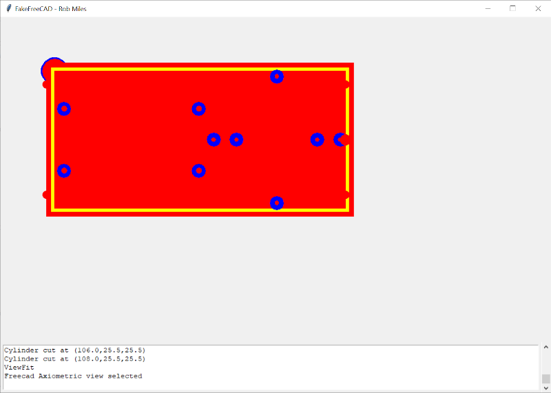
You can read more about it on the GitHub page, but essentially, you wrap your Python code into a function, import FakeFreeCAD, and then add a little boilerplate code and call the function. Here’s a partial example of a test function:
from FakeFreeCad import *

### code from FreeCad starts here
### Make it into a function that can be called to make the part

def makePlate():

   plate = Part.makeBox(800,600,100)
   hole = Part.makeCylinder(200,200,Base.Vector(400,300,0))
   plate = plate.cut(hole)

   Part.show(plate)
   Gui.SendMsgToActiveView("ViewFit")
   Gui.activeDocument().activeView().viewAxometric()

### End of the FreeCad code
You’ll have to dig through the code to see how many things are supported, but it would probably be pretty easy to add anything that’s missing. Naturally, having debugging support in FreeCAD would be better, but this is a pretty handy hack to get you most of the way there.
FreeCAD has gotten a lot better in recent years. We’ve seen a lot of talk about its parametric capabilities. If you want a basic tutorial, we’ve had those, too.


Looks like you’ve got a bit of an indentation problem there…
Sigh… WordPress…
how do you fail at rectangle in cad? Realistically you will spend more time debugging the macro than the once off failure .. if its a repeated use create a library element so you only design it once and move on with life … its cad you can scale it with a command and a number. Not everything needs to be recomputed from scratch.
I don’t think he needed to debug making a rectangle. But he is showing you how to do it without cluttering up with a bunch of details specific to what he is really doing which will be different that what someone else is doing. There are actually quite a few use cases for macros, depending on what you are doing.
Does it still crash randomly? Last time I’ve heard “FreeCAD has gotten a lot better in recent years.” I’ve downloaded it, tried making a slot in a box and it crashed.
It doesn’t crash randomly. It crashes deterministically. It’s just that you don’t always apply the same operations in the same order. But it’s getting better, and while 0.17 was completely unusable for me, 0.19 is a lot more stable. When you start using experimental features, it’s less stable, but I never experienced a corrupted file and it loads fast, so it’s ok for me to relaunch it.
> It’s just that you don’t always apply the same operations in the same order.
And when you throw a coin, result depends on how you throw it. For all intents and purposes, typically the final effect is the same, “as close to random as you can get”. I wish I had enough free time to debug such issues.
Sorry, I use FreeCAD for complicated, real world designs, every day (as do plenty of people world wide). Sure it has warts. But, it is a capable tool…if you make the effort to learn how to use it. It has different paradigms and workflows, it doesn’t think for you. And, at least on Linux, I have no random or regular crash issues with 0.19 (for almost 2 years).
I have not seen it crash on any of the simple projects that I have done. As a ‘newbie’ to freecad, I’d think I’d be more prone to ‘hitting the wrong thing’. So far .18 and now .19 have been rock solid (Linux based of course) and easy to use. My problem of course is experience to know which is the ‘right’ or more efficient way of doing things even though I do get the job done and get a dxf created! Glad there are some good video tutorials out there that really helped me get started.
Yes, that’s what I’ve seen even with .17. Some people say it just works, some say it crashes. It crashed for me both on linux and windows. Then after .18 crashed on windows I didn’t even try anymore. As for workflows – after learning for a while they are very usable. I wish I could use it, but I have to stay on openscad plus some occasional python for generating more complex surfaces.
I bet if all the people who say it crashes and all the people who say it doesn’t shared their video card make/model and Xorg configurations a pattern would emerge.
FreeCAD doesn’t crash for me. I’ve been using it for years. For the last ~2 years 0.19. It is quite capable. As usual with complicated software it takes effort to learn.
Debugging python code is simple when linked with vscode. Then you have breakpoints, stepping, variable viewing…all the the debugging features of vscode.
Getting it to do what I want has been frequently challenging, as the relatively rapid development does mean documentation and guides doesn’t always match the version, doesn’t help that more distros are packaging a really old version too – which it can take a wihle to notice, and the older ones are less stable…
But I’ve not had any trouble with crashes in ages either. And the latest version has been for me very good. Its mostly the distro’s packaging up old versions that causes headaches I’d say.. Though I’ve never tried it on anything but LInux maybe Windon’t really doesn’t handle it well, I don’t want to find out myself…
Yeah, especially the realthunder Link Branch is quite capable nowadays. I use it instead of the 0.18.4 stable or the official 0.19.
One thing which makes FreeCAD a PITA to use (compared to the more capable expensive suites like Solidworks, Solid Edge, Inventor, … which I use on a daily basis on my day job) for complex models is the very annoying Topological Naming Problem. Faces/features get internally renamed after you apply changes to them, breaking all the stuff dowan the feature tree which has constraints to them.
You’ve got 20 different actions in your feature tree and decide to delete a chamfer or some other extrusion/cutout/whatever? Bam, your part is (most certainly) gone after that feature.
The cheap excuse of users not used to a professional suite always is: chamfers and radiuses are purely cosmetic, add them as last steps. I call BS here, there are no purely cosmetic actions. Deleting a chamfer shouldn’t destroy “all” the following constraints to faces the chamfer might have touched in a way. Another “workaround” is using master sketches or even a new plane for every feature. Which, btw must be constrained to the original XYZ planes to be robust against changes… This is not how engineers work.
As mentioned, the realthunder branch of FreeCAD does a much better job here, though not perfect yet.
But, it is FREE SOFTWARE after all, I am not a programmer and because of that I can’t help making the software better, besides a donation to the staff here and there. So I am not complaining. I like it for what it is and use it often anyway.
With history based CAD like , gluing sketches onto part geometry makes it harder to edit complicated parts later. It has been and is considered bad practice. Of course, TNP makes it worse still, no argument there. There seems to be a mindset that the capability to slap sketches and planes on any and every face/edge/whatever with reckless abandon allows the capability to be added to the “best practices” list. It certainly won’t go on mine, even after TNP goes away.
It was supposed to say: “With history based CAD like [insert your favorite commercial or opensource software name here]”…who knew chevrons mean something special to Askimet.
Valid arguments there, Mac.
To put things into perspective: I work in a team, we build machines in the multiple 100k€ range. This is not a brag-post (hard for me to get it across, I’m not a native-English guy :) )
At my job I am supposed to create parts which history can easily be understood and altered by anyone after me.
This includes (most of the time) practices like:
– always link geometry to the parts base coordinate system
– absolutely NO external references (external = from other parts or assemblies). Those are disabled by default in all the companies I worked for.
– as little “grabbing edges and geometry” for references as possible
– …
But let’s be real here. We need to get stuff done in time, you use shortcuts when there are shortcuts. I know not a single engineer who creates a parallel offset plane referenced to a base plane first, to add holes to a parts face. You add them to the face directly. And if that face already had chamfered edges, the holes might get corrupted, if the TNP comes into play. CAD systems need a certain level of robustnes. And it is little things like that which can cost you hours of work to repair stuff if that robustnes is not there.
There’s always textbook-engineering and real-life. And everything in between for sure!
And, if those are company policy and you did a design review based on that policy, what would the outcome be? :) I’m an engineer and I create my sketches with offsets as needed, done it for years (decades actually…), second nature (planes only when planes make sense). So now you know one engineer that does. ;)
“And, if those are company policy and you did a design review based on that policy, what would the outcome be? :)”
We really do our best, to create robust parts and assemblies. The effort shows best, if you can grab complete sub-assemblies, change them to your new needs and reuse them without a big hassle. And to be honest, most of the time this is the case. Phew!
If the program helps us with “integrated robustness”, we will happily include that into our daily work :)
“So now you know one engineer that does. ;)”
“Know” may be a bit far stretched, but I’ll tell my collegues that I had a internet-convo with a textbook-engineer who does the “planes magic” :P
Cheers, Jan
Ironically, I seem to remember VBA in Word having a pretty decent debugger, as well as possible interaction with the VB6 IDE if installed? It’s been a long time…